Spare parts and accessories
Manual b maXX
®
BM1000
Document No. 5.07003.04
123
of 174
B
m Function explanation
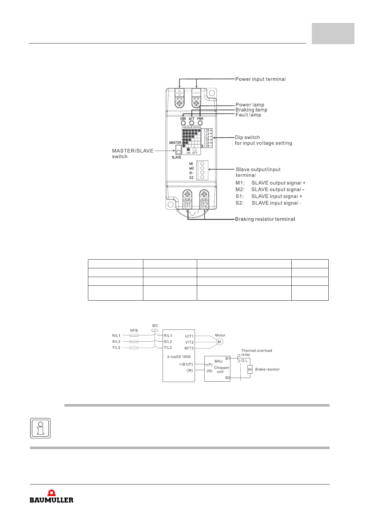
Figure 63: Parts of chopper unit
n Terminals
m Basic wiring diagram
Figure 64: Wiring diagram chopper unit
Terminal symbol Wire gauge AWG/mm
2
Terminal
Power input circuit +(P), -(N) 20~22AWG/0.5~0.3mm
2
M4 screw
Braking resistor B1, B2 20~22AWG/0.5~0.3mm
2
M4 screw
SLAVE circuit M1, M2
S1, S2
24AWG/0.2mm
2
M1, M2, S1, S2 with shielded wires
M2 screw
NOTE
Do not wire terminal -(N) to neutral point of power system.



 To Next Page