Chopper units and braking resistors
Manual b maXX
®
BM1000
Document No. 5.07003.04 Baumüller Nürnberg GmbH
124
of 174
B.1
m Operation explanation
n For safety consideration, install an overload relay between the chopper unit and the
braking resistor. In conjunction with the magnetic contactor (MC) prior to the drive,
it can perform complete protection against abnormality.
n The purpose of installing the thermal overload relay is to protect the braking resistor
from damage due to frequent braking, or due to braking unit keeping operating re
-
sulted from unusual high input voltage. Under such circumstance, just turn off the
power to avoid damaging the braking resistor.
n Please refer to ZSelect a chopper unit /braking resistor– on page 120 for the spec-
ification of the thermal overload relay.
WARNING
The following may occur, if you disregard these safety notes:
m serious personal injury m death
Do not proceed with wiring while power is applied to the circuit.
The wire gauge and distance must comply with the electrical data.
The +(P), -(N) terminals of the b maXX
®
BM1000, connected to the chopper unit, must be
confirmed for correct polarity lest the drive and the chopper unit be damaged when power
on.
When the chopper unit performs braking, the wires connected to +(P), -(N), B1 and B2
would generate a powerful electromagnetic field for a moment due to high current passing
through. These wires should be wired separately from other low voltage control circuits so
that do not make interference or mis-operation
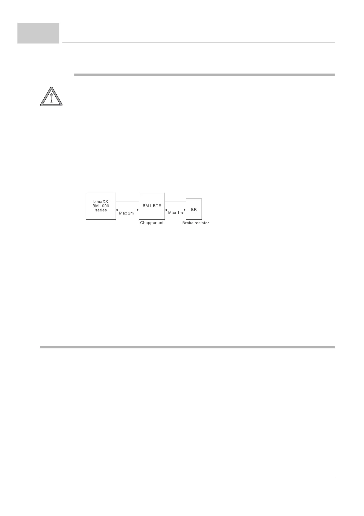
Wiring distance
Figure 65: Wiring distance chopper unit
Inflammable solids, gases or liquids must be avoided at the location where the braking re-
sistor is installed. The braking resistor had better be installed in individual metallic box with
forced air-cooling.
Connect the ground terminal to PE. The ground lead must be at least the same gauge wire
as leads +(P), -(N).
Please install the braking resistor with forced air-cooling or the equivalent when frequent
deceleration braking is performed (over 10
% ED).
To avoid personal injury, do not connect/disconnect wires or regulate the setting of the
chopper unit while power on. Do not touch the terminals of related wiring and any compo
-
nent on PCB lest users be damaged by extreme dangerous DC high voltage.
The ring terminals are suggested to be used for main circuit wiring. Make sure the terminals
are fastened before power on.
 Loading...