80-0000010B OM
172
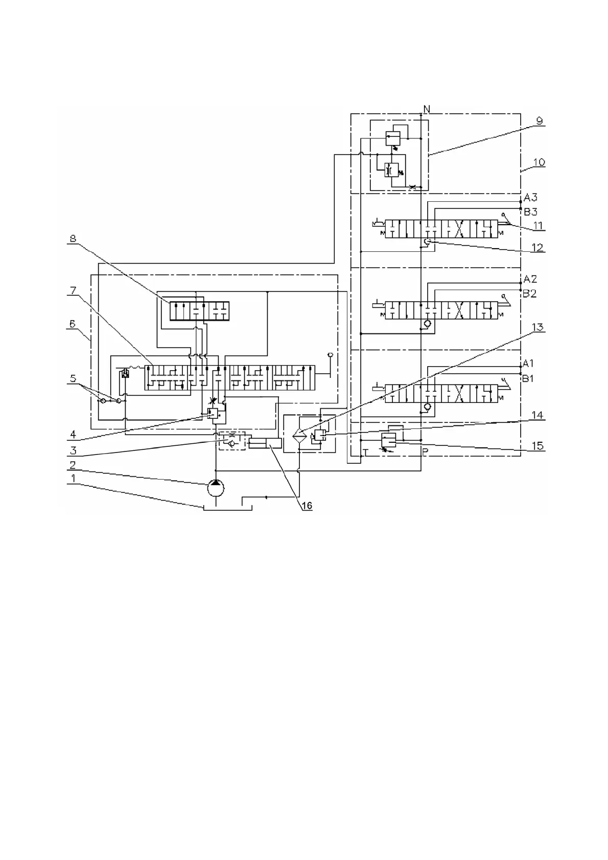
HLL hydraulic circuit diagram with the distributor РП70-1221.1С is shown in figure
3.15.4.
1 – tank; 2 – pump; 3 – redarding valve; 4 – priority valve; 5 – back-flow valve;
6 – draft (position) control; 7 – sleeve; 8 – spool; 9 – by-pass valve; 10 – distributor
РП70-1221.1С; 11 – spool; 12 – back-flow valve; 13 – filter of the hydraulic system;
14 – filter valve; 15 – safety valve; 16 – cylinder.
Figure 3.15.4 – HLL hydraulic circuit diagram with the distributor РП70-1221.1С installed.