Connecting Output Devices
The control panel has 2 Non-supervised outputs, 4 Bell outputs (super-
vised) and 8 Alarm Repeat outputs (one for each Software zone).
The control panel can manage two FC200/6OUT Output Expanders (ac-
cessory items) which provide 6 Bell outputs each.
NOTE: Output devices can be connected to the loops by means of Output
modules.
Bell Outputs
The Bell outputs are indicated by the letter "C" and their address number.
You can fully customize the activation modes and times of the Bell outputs.
+
The address of the Output-Expander Bell outputs depends on the Output-
Expander address.
+
The terminal marked "C" is a Type C Output and not a Bell output.
The Type C Output is a Non-programmable, Supervised output.
The Bell outputs can be forced to standby status by means of the SI-
LENCE button. Once an alarm has been acknowledged, you can silence
the audible signalling devices and leave the visual signalling devices active
until the alarm conditions cease.
For example, a connection similar to the wiring diagram in figure 14 will ac-
tivate the Flasher, the Bell and the visual and audible signalling device of
the Self-powered Siren in the event of an alarm.
Using the SILENCE button will stop the horn but not the flasher, which will
continue to signal Alarm status until the RESET button is pressed.
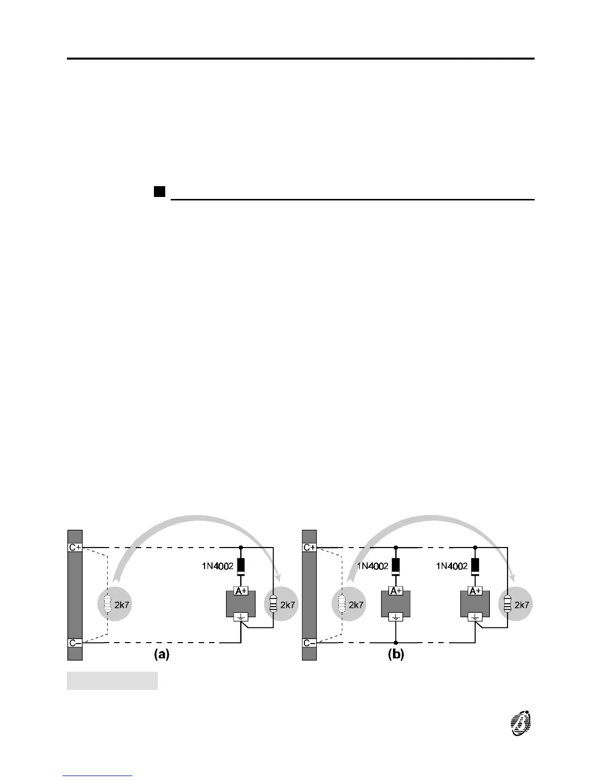
Figure 13 Wiring diagram of the connection of a single device (a) and several devices
(b) to Bell outputs (device activated by positive (27.6 V) on terminal [A+]).
30 Analogue Fire Control Panel FireClass200