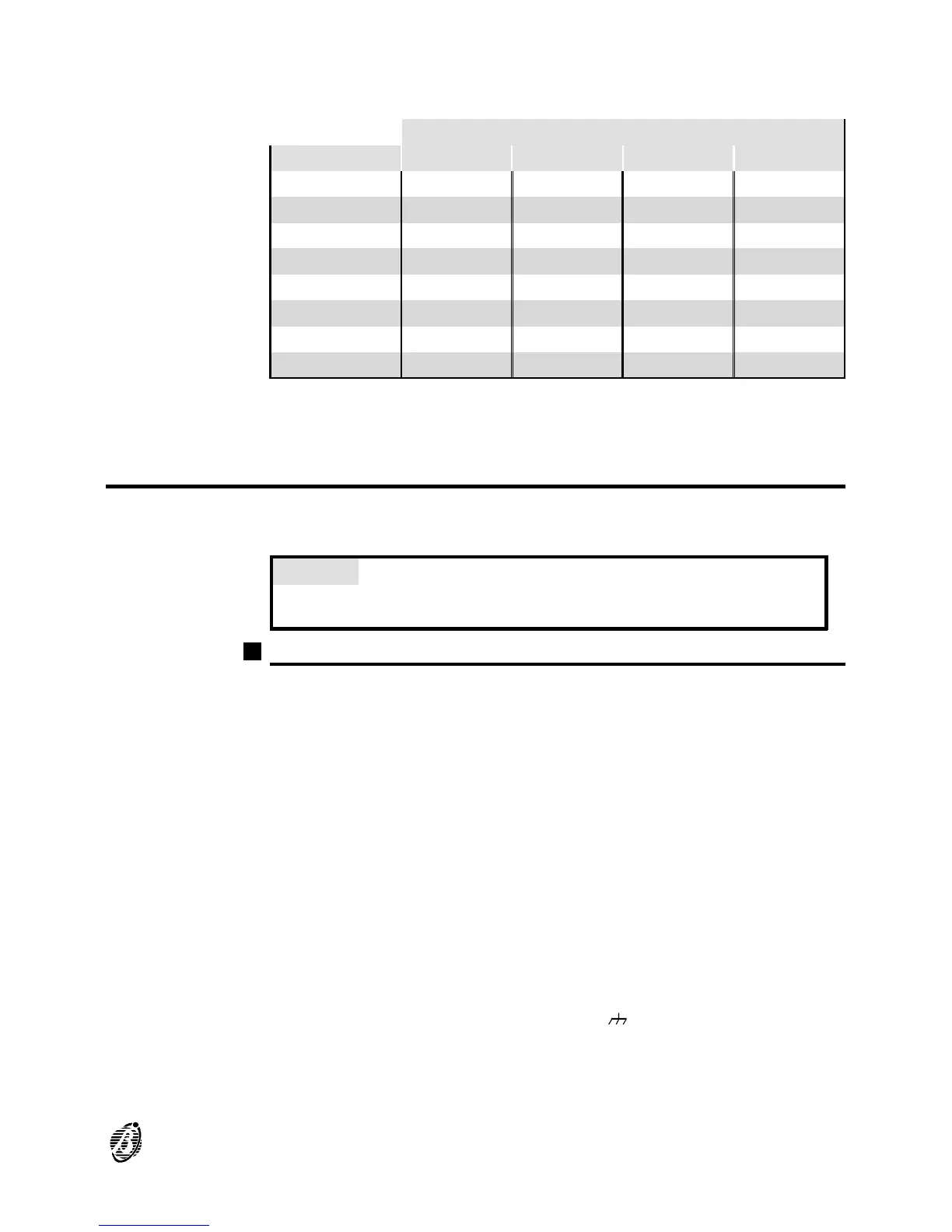
4. Using the microswitches 55, assign an address to the repeater panel (refer
to the following chart).
MICROSWITCH No.
ADDRESS No. 1 2 3 4
1 OFF OFF OFF OFF
2 ON OFF OFF OFF
3 OFF ON OFF OFF
4 ON ON OFF OFF
5 OFF OFF ON OFF
6 ON OFF ON OFF
7 OFF ON ON OFF
8 ON ON ON OFF
+
You must assign a different address to each repeater panel.
Completing the Connections
+
Use a shielded cable ---- connect one end to the control panel ground and
leave the other floating.
CAUTION Separate the low voltage wires (24V) from the high voltage
wires and make two wire bunches. This will prevent stray wires from
coming into contact with other wires and/or components.
Main board terminals
[L1B] Loop 1 communication IN.
[L1A] Loop 1 communication OUT.
[L2B] Loop 2 communication IN.
[L2A] Loop 2 communication OUT.
+
Each loop supports 99 analogue detectors and 99 analogue devices (Input
modules, Conventional Zone modules, Manual callpoints, Output modules
and Sounders).
[LC] Conventional Input Line - Supervised and Silenceable ---- This line sup-
ports 30 conventional fire devices (RF501t Optic Smoke detectors, RT
101/102 Heat detectors, Manual callpoints, Gas detectors----maximum 3).
Connect terminal 10[+] to ground (terminal 9[ ]) using a 2,700 ohm resistor
(red-purple-red-gold). A 680 ohm resistance (normal value for Fire detectors)
parallel to the 2,700 ohm resistor will activate the programmed actions and
preset times of the Conventional Line outputs and the Non-supervised output
(terminals CM1, NC1 and NO1).
INSTALLATION 23