PARTS IDENTIFICATION
This chapter holds the full description of the main components and LEDs
of the FireClass200. In most cases, the numbers in boldface refer to the
parts shown in the tables and figures.
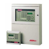
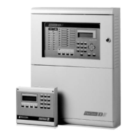
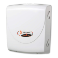
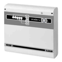
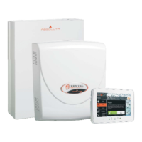
Main unit (FireClass200)
The Flashing status of certain LEDs is not dealt with in the following ta-
ble, as it signals that the assigned event occurred and ended before the
last rearming operation.
LED MEANING
ALARM ON: the control panel is in ALARM status.
MORE ALARMS ON: presence of more than one alarm condition.
PRE-ALARM
FLASHING: PRE-ALARM status - the sensors have detected an alarm
condition. The Outputs will be activated when the PRE-ALARM delay
ends.
TELECOM ON: the control panel is physically connected to the telephone line.
MAIN POWER
OFF: mains failure. Mains power must be restored before the batteries
empty.
WALK TEST
FLASHING: Walk Test mode on a Software Zone; an alarm condition on
the Zone in question will generate an alarm status on the assigned
Outputs for approximately one second.
DISABLED ON: at least one device is disabled.
NIGHT ON: the control panel is operating in NIGHT mode.
DAY ON: the control panel is operating in DAY mode.
FAULT
ON: presence of at least one fault condition; the type of fault will be
signalled by the associated LED and/or on the display.
MAINS
ON: mains failure; the standby batteries will takeover the power supply to
the control panel. This LED is complementary to the green MAINS-
POWER LED, and will continue to signal the fault event after mains
power has been restored (memory).
LOW BATTERY
ON: low batteries; proper functioning of the control panel cannot be
guaranteed in the event of black-out. Wait several hours, if the LED stays
ON the batteries are not rechargeable and must be replaced
BATTERY FAULT ON: batteries are completely empty or not connected - check fuse 41
GROUND ON: voltage leak to ground - check connection insulation.
FUSES
ON: burnt fuse (fuse 41 or 42) - the fuse concerned will be indicated on
the display.
LOGIC UNIT ON: "blocked" microprocessor - call Installer for service.
PARTS IDENTIFICATION 11