You can use 2 or 4 wires for the loop connections.
NOTE: The loop connection type must be specified during the program-
ming phase.
Figure 9 illustrates the 2 wire connection to Loop 1.
Figure 10 illustrates the 4 wire connection to Loop 1.
+
The 2 wire connection does not permit more than 32 detectors per loop.
+
The 4 wire connection does not permit T connections.
Connecting Conventional Devices
Connect Conventional devices to terminals 9[ ] and 10[LC+].
Fire detectors Connect the Conventional Fire detectors in parallel to terminals [LC+] and
[ ]. The resistor (2,700 ohm) connected to these terminals must be
moved to the terminals indicated in the instructions of the last device on
the Conventional Line (see fig. 10a).
Manual
callpoints
Connect the Common (C) and the Normally Open (NO) terminals of the
Manual callpoint in parallel to terminals [LC+] and [ ]. When pressed, the
callpoint must not be shorted but must have a 680 ohm resistance. If
the callpoint does not have a 680 ohm resistor, connect one externally. If
the manual callpoint is the last device on the Conventional Line, the EOL
resistor must be connected as per figure 10a.
NOTE: Conventional devices can be connected to the loops by means of
Conventional Zone modules.
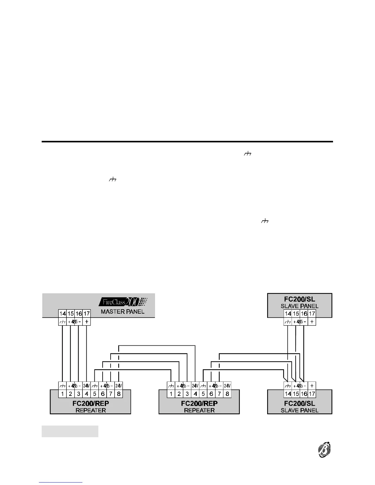
Figure 11 Wiring diagram of Repeater and Slave Panels connected to the RS485 network
28 Analogue Fire Control Panel FireClass200