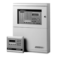
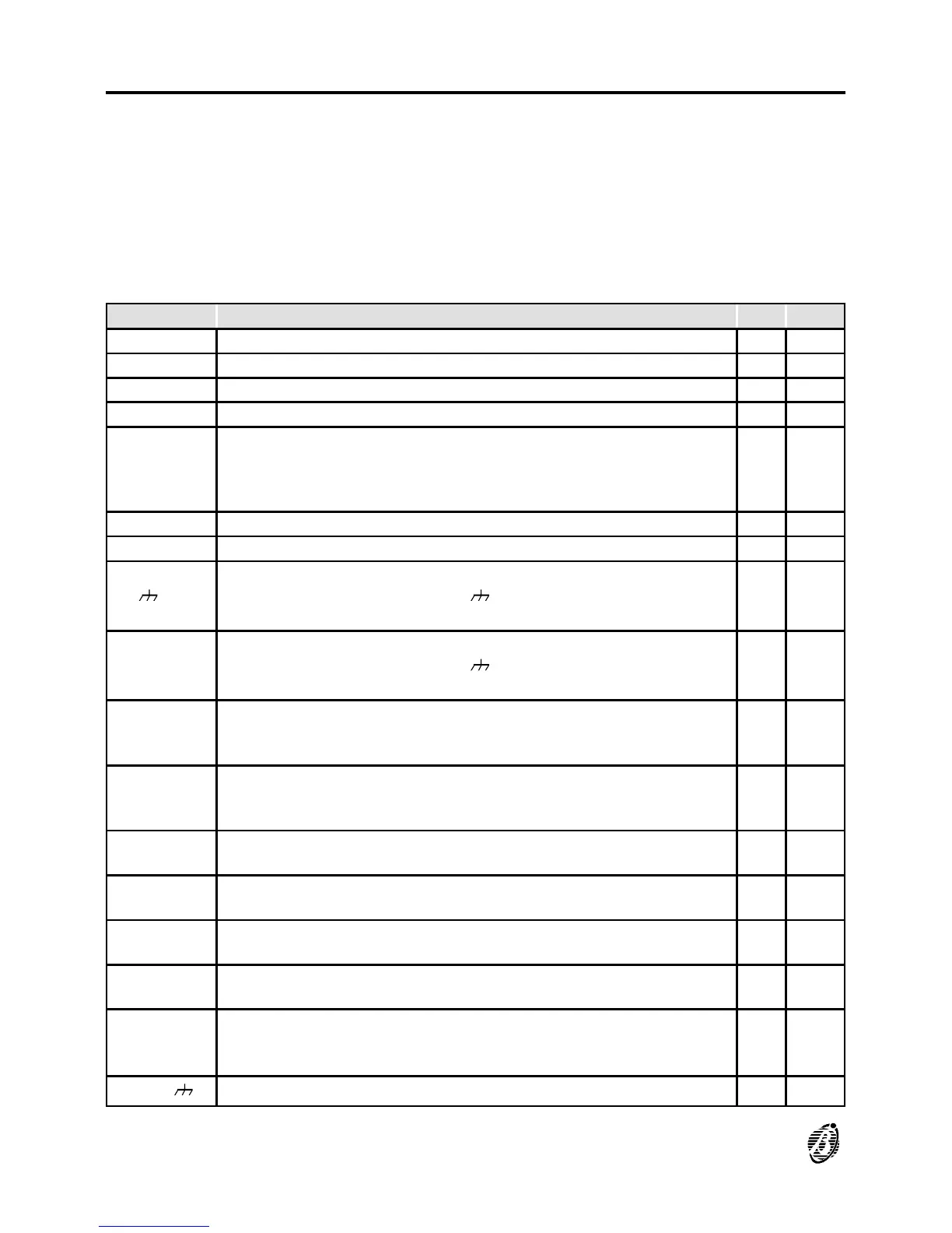
Terminals
The following charts hold:
Ø a brief description of the terminals on the Main Board, Output Expanders
and Repeaters;
Ø the voltage present during the different conditions of each terminal;
Ø the maximum voltage (in amperes) that can circulate on each terminal.
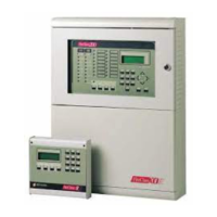
Main board
TERM. DESCRIPTION v(V) i(A)
[L1B] LOOP 1 IN -- --
[L1A] LOOP 1 OUT -- --
[L2B] LOOP 2 IN -- --
[L2A] LOOP 2 OUT -- --
[LC+]
CONVENTIONAL LINE:
balanced line with 2700 ohm è control panel in standby
unbalanced line è Conventional Zone activated
line in short-circuit or open è fault on the Conventional Zone
-- --
[EX] RESERVED OUTPUT -- --
[+485--] SERIAL BUS -- --
14[ ] 17[+]
REPEATER POWER SUPPLY:
negative present on terminal 14[ ]
positive present on terminal 17[+]
0
27.6 3 (3)
[AUX]
24 V AUXILIARY POWER SUPPLY:
negative present on terminal 19[ ]
positive present on terminal 19[+]
0
27.6 3 (3)
[CM1]
[NC1]
[NO1]
FAULT ALARM OUTPUT - NON Controlled:
standbby è [CM1] connected to [NC1] with [NO1] open
in the event of fault è [CM1] connected to [NO1] with [NC1] open
-- 5
[CM2]
[NC2]
[NO2]
FIRE ALARM OUTPUT - NON Controlled:
standby è [CM2] connected to [NC2] with [NO2] open
in ALARM Status è [CM2] connected to [NO2] with [NC2] open
-- 5
[C]
POSITIVE FIRE ALARM OUTPUT - Controlled:
in ALARM Status è positive on [+] and negative on [--] 27.6 1.5 (3)
[C2] [C3]
[C4]
PROGRAMMABLE OUTPUTS - Controlled:
output active è positive on [+] and negative on [--] 27.6 1.5 (3)
[REM]
LOGIC UNIT BLOCKED:
Logic Unit blocked è terminal to negative 0 1
[DEF]
DEFAULT DATA:
Control panel programmed with default data è terminal to negative 0 1
[OC1]
↓
[OC16]
ZONE ALARM:
corresponding zone in standby è terminal open
zone in ALARM Status è terminal to negative
0 0.1
36-45[ ]
GROUND
0 --
96 Analogue Fire Control Panel FireClass200