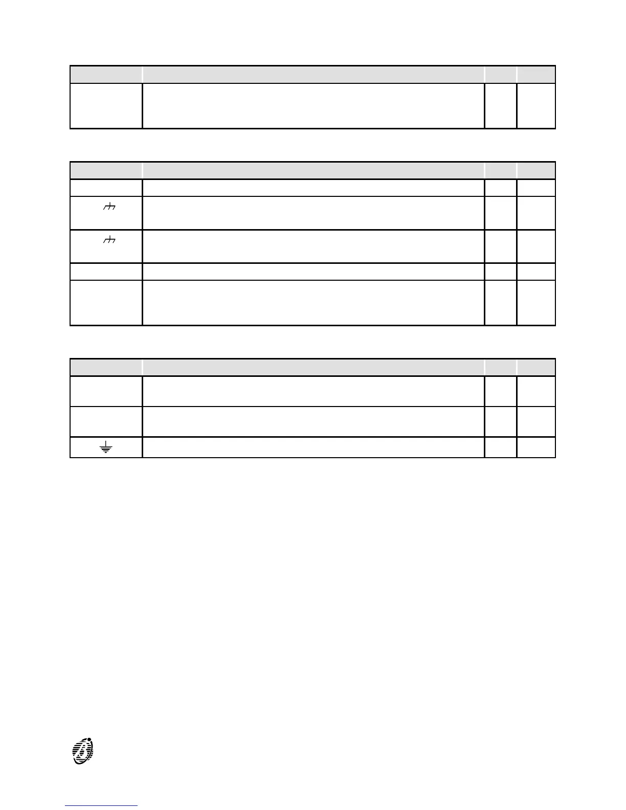
Output Expander
TER. DESCRIPTION v(V) i(A)
[C5/11]
↓
[C10/16]
PROGRAMMABLE OUTPUTS - Controlled:
output active è positive on [+] and negative on [--]
27.6 1.5 (3)
Repeater
TER. DESCRIPTION v(V) i(A)
[+485--] SERIAL BUS -- --
1[ ]
4[24V]
POWER SUPPLY (input):
terminals for the power supply to the Repeater
27.6 0.18
5[ ]
8[24V]
POWER SUPPLY (output):
terminals for the power supply to the next Repeater
-- --
19[+] POSITIVE 27.6 0.2
[Z1]
↓
[Z16]
ZONE ALARM:
zone in standby è corresponding terminal open
zone in ALARM Status è corresponding terminal to negative (4)
-- 0.01
Telecom Module
TER. DESCRIPTION v(V) i(A)
[LE1]
[LE2]
TERMINALS FOR THE CONNECTION of the external telephone
lines
/ /
[LI]
TERMINALS FOR THE CONNECTION of other telephone-line
sharing devices (answerphone, telephone, fax modem, etc.)
/ /
[ ]
Earth Terminal
0 /
(3) The total current absorbed by terminals 17[+], 19[+], 26[+], 28[+], 30[+],
32[+] on the Main Board, and by terminals [+] of the Output Expander,
must not exceed:
2 A for the FC200 control panel;
1 A for the FC200/S - FC100 control panel.
(4) Terminals from [Z1] to [Z16] of the Repeater must be connected to nega-
tive by a 2700 ohm resistance, and asbsorb 0.01 A in the connection to a
LED.
QUICK GUIDE 97