Amplifier & Channel Labels
Element Description
The labels of an amplifier and its input and output channels are shown in a clear
structure. All labels can be edited. Changes are immediately adopted in the different
panels and windows (amplifier control panel, flow diagram, overview).
CAUTION: Using * (asterisk) and/or = (equal) signs in a name is not permissible.
Control Port
A control port offering two control inputs and two control outputs is located on the amplifier’s rear panel. The
functions of these inputs and outputs can be randomly programmed. For example, the control inputs (GPI) can be used
for power- on / stand-by or preset switching as well as for changing parameters. The control outputs (GPO) are for
signaling inter- nal statuses. They can directly trigger LEDs, control lamps or relays. In the Supervision & Test window
the states of the control inputs are displayed and you have the possibility to switch the control outputs manually. For
more information and electrical specifications of the control port, please refer to the amplifier manuals.
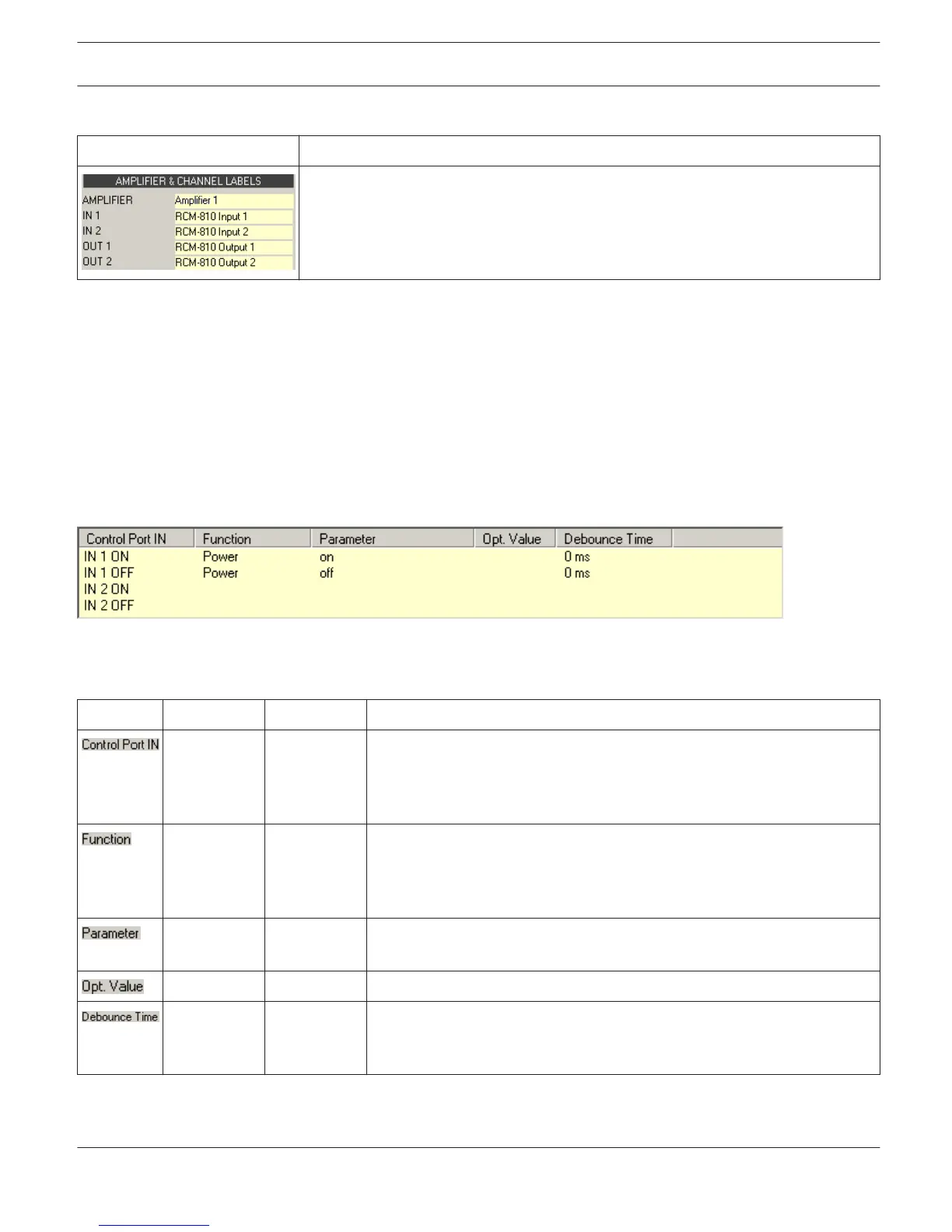
Control Inputs: Each status change of a control input can trigger a function. Different functions can be assigned for the
opening (OFF) or closing (ON) of a contact.
Example:
This example shows the programming of two control inputs where IN1 switches the amplifier on or off.
– IN1 ON: Power on (closing the contact of control input 1 switches the amplifier on)
– IN1 OFF: Power off (opening the contact of control input 1 switches the amplifier to stand-by)
Element Default Range Description
IN 1 ON
IN 1 OFF
IN 2 ON
IN 2 OFF
This provides a listing of the two control inputs and their statuses ON and
OFF. The entries in the corresponding lines specify the action when
closing (ON) or opening (OFF) a contact.
(empty) This column allows assigning functions to a control input’s statuses.
Clicking the desired line in the Function menu opens a dialog field that
shows all accessible functions. The table "Input and Receive Job
Functions" lists all functions together with their individual settings.
(empty) Here you can set the different function parameters. For more information,
please refer to the table "Input and Receive Job Functions".
(empty) Certain functions allow specifying optional parameter values.
0 ms 0...10027 ms
16.33 ms
Steps
Here you can program delay or debouncing times. Following a status
change the assigned function is initiated after the set time interval has
past.
IRIS-Net
REMOTE AMPLIFIER | en 294
Bosch Security Systems B.V. User Manual 2017.05 | 3.20 | F.01U.119.956