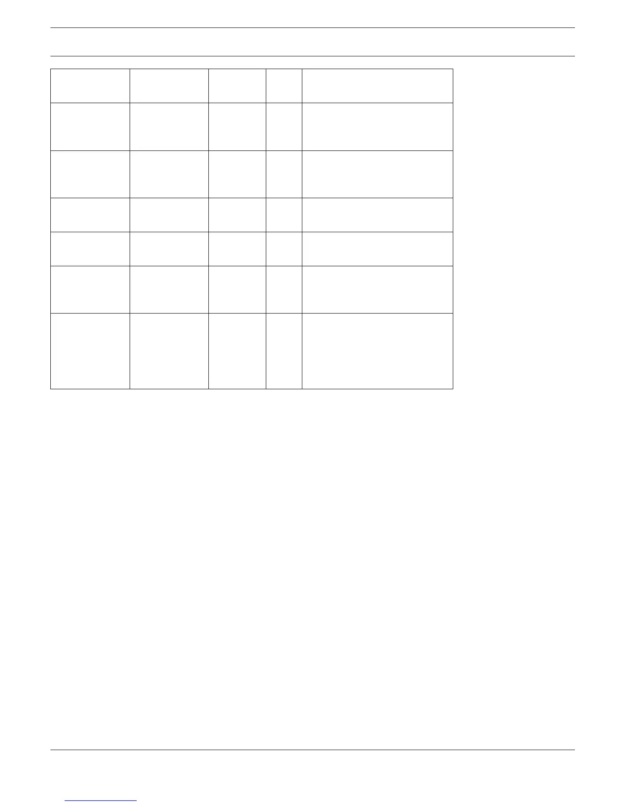
Power
X
Power On
Power Off (Standby)
Absolute Mute 0 = not
muted, 1 =
muted
X
Set parameter value reached or
exceeded Set parameter value
declined
Temp Temperature in
°C
X
Set temperature reached or
exceeded Set temperature
declined
VU Out 1...n Level in dB
X
Set level reached or exceeded
Set level declined
GPI IN 1, IN 2
X
Control input 1 / 2 closed (ON)
Control input 1 / 2 open (OFF)
Stateflag All internal fault
conditions
X
Single or several stateflags set
None of the selected stateflags
set
Memoflag Enable for
selected flags as
well as bit-
pattern of flags
1 - 16
X
Memory flags match the
selected bit-pattern Memory
flags do not match the selected
bit-pattern
Supervision & Test
The Supervision & Test Dialog integrates functions for testing and monitoring power amps. Status indicators for
general power amp operation, the amplifier channels and the load connected, indicate whether everything is okay or
where failures occurred. You have the option to choose, which errors are combined and indicated in a general fault
message.
A click on the Supervision & Test tab selects the page while in the Setup & Control Window.
Error Detection
Error detection lists the individual STATE of fault indications. Errors collected are amp failure, channel failure, cable
interruption, short-circuits, load deviation, ground fault, erroneous communication via the CAN bus as well as fault
messages of other amps. A green STATE indicator signals normal operation. A red STATE indicator signals error
detection.
If one of the corresponding DETECT boxes is marked, the state of that message is additionally included in the COLLEC-
TED ERROR STATE. When activating the HOLD option, the indicator stays red after the occurrence of an error. If the
HOLD option is not active, indication returns to green, once the fault is not detected anymore. Pressing the CLEAR but-
ton in the COLLECTED ERROR STATE line resets the indicator from red to green and stored errors are deleted. The
COLLECTED ERROR STATE indicator resembles exactly the Amplifier State indicator of the System Check Window. The
collected fault state message can be outputted via a control output. For detailed explanation please refer to chapter
Config & Info.
IRIS-Net REMOTE AMPLIFIER | en 298
Bosch Security Systems B.V. User Manual 2017.05 | 3.20 | F.01U.119.956