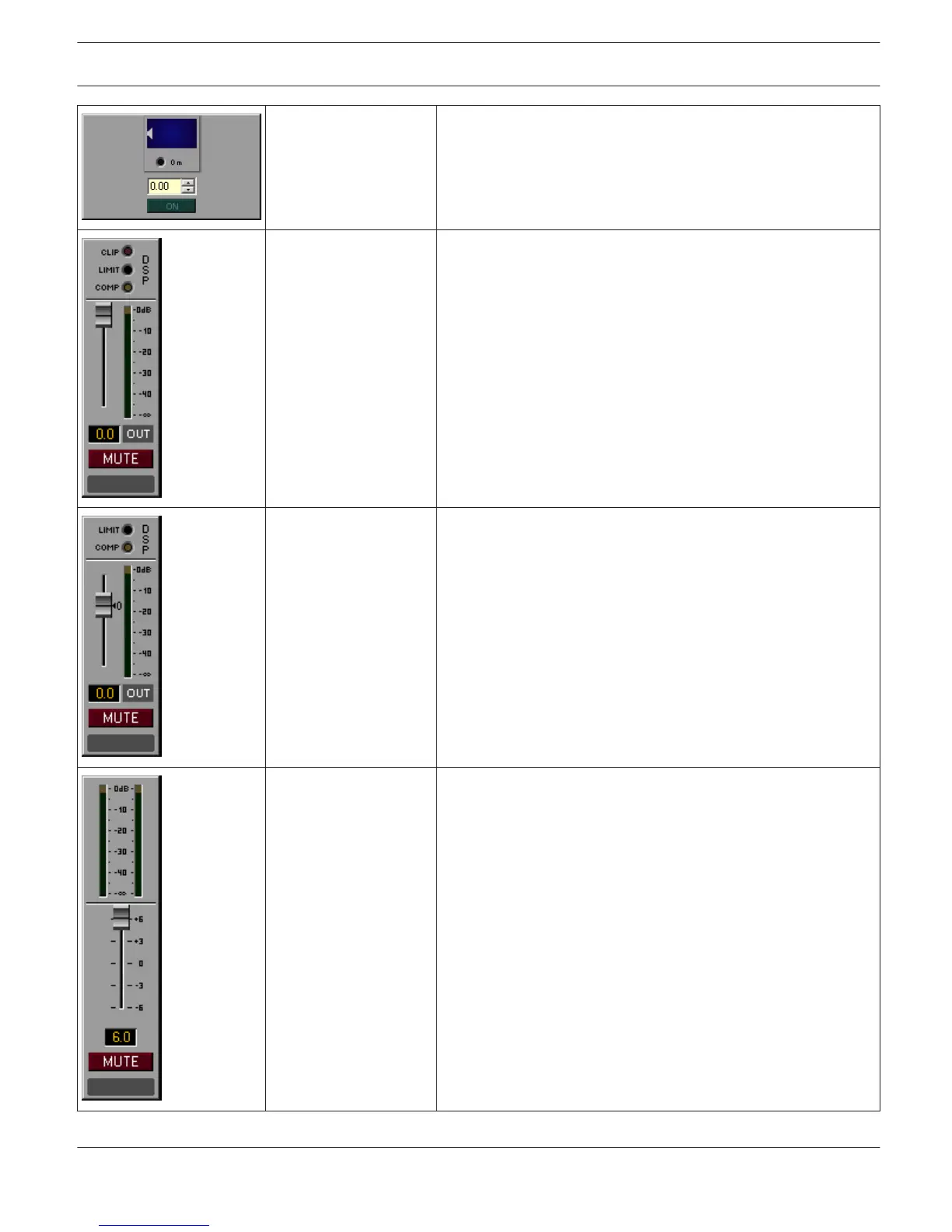
Delay_Panel_03 Delay value and bypass for the master delay of a remote amp.
Possible Connections: RCM- 24-Amp-Channel, RCM-26-Amp-
Channel
Group_Panel_01 These three LEDs indicate clipping (CLIP) or whether the limiter
(LIMIT) or the compressor (COMP) of the DSP is active. Fader
and MUTE buttons for controlling and LED bar graph meter for
monitoring the amp’s output levels (maximum of both
channels). Possible Connections: RCM-24-Amp, RCM-26-Amp
Group_Panel_02 These two LEDs indicate whether the limiter (LIMIT) or the
compressor (COMP) of the DSP has been activated. Fader and
MUTE button for controlling the amplifier. The LED bar graph
meter is for monitoring the amp’s output levels (maximum of
both channels). Clicking onto the ”0” marking resets the fader
to 0 dB. Possible Connections: RCM-24-Amp, RCM-26- Amp
Group_Panel_03 Indicates the output levels of the two channels. Fader and MUTE
button for controlling the amplifier. Possible Connections:
RCM-24-Amp, RCM-26-Amp
IRIS-Net IRIS-Net | en 32
Bosch Security Systems B.V. User Manual 2017.05 | 3.20 | F.01U.119.956