Group_Panel_GainTrim_
01
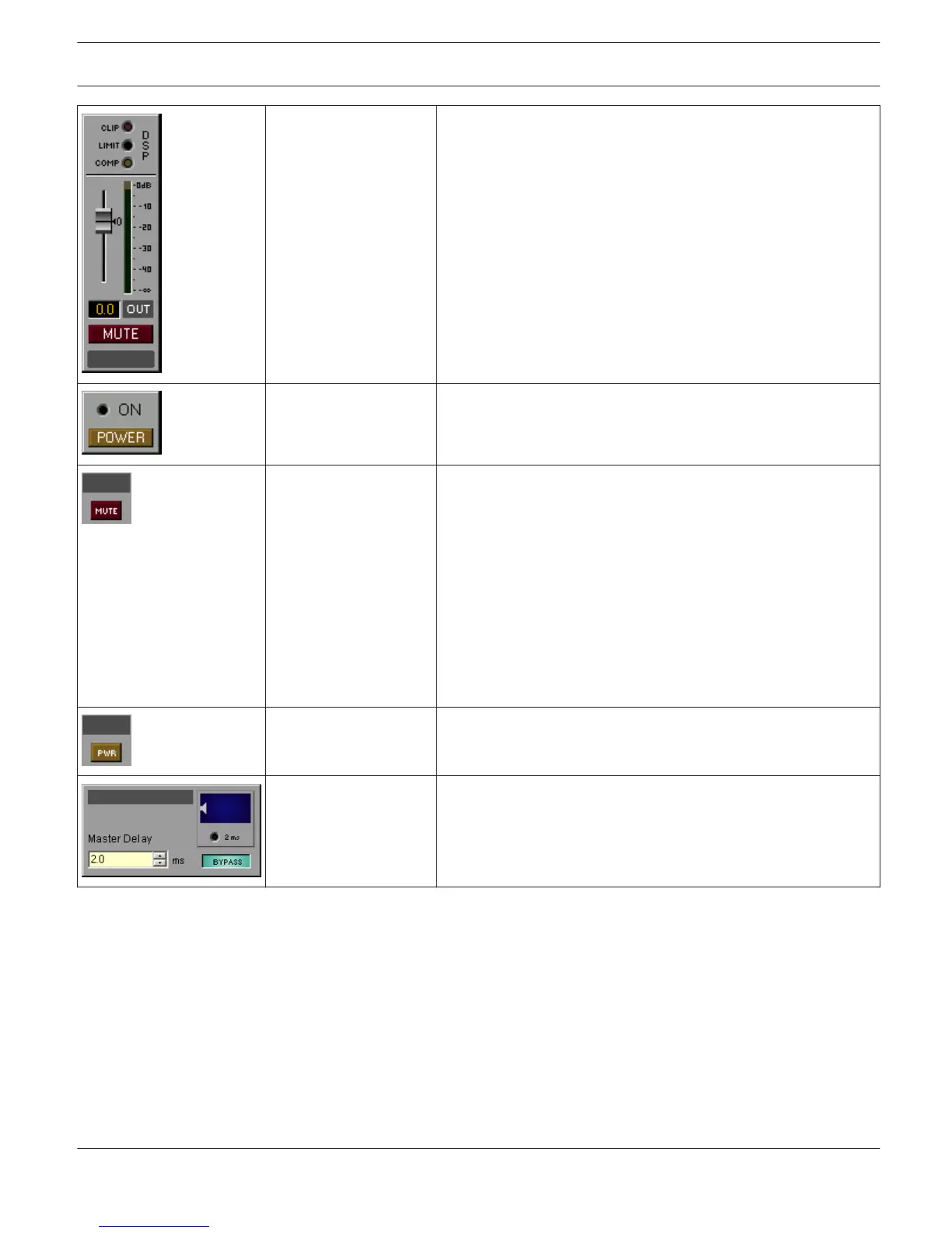
These three LEDs indicate clipping (CLIP) or whether the limiter
(LIMIT) or the compressor (COMP) of the DSP is active. Fader
and MUTE button for controlling the amplifier. The LED bar
graph meter is for monitoring the amp’s output levels (maximum
of both channels). Clicking onto the ”0” marking resets the
fader to 0 dB. Possible Connections: RCM-24- Amp, RCM-26-
Amp
Group_POWER_01 Power-on/off a group of amps with safety dialog when powering
off. Possible Connections: RCM-24-Amp, RCM-26-Amp
Labelled_MUTE_02 MUTE button with label field. Possible Connections: RCM-24-
Amp-Channel, RCM-26-Amp- Channel, N8000.DSP.AnalogIn.ChX,
N8000.DSP.AnalogMicIn.ChX, N8000.DSP.Analog Out. ChX,
N8000.DSP.AutoMixer.ChInX, N8000.DSP.AutoMixer.ChOutX,
N8000.DSP.CobraNetIn.ChX, N8000.DSP.CobraNetOut.ChX,
N8000.DSP.DigitalIn.ChX, N8000.DSP.LSpkBlock.ChX,
N8000.DSP.Matrix.InputX, N8000.DSP.Matrix.OutputX,
N8000.DSP.MatrixRouter.InputX,
N8000.DSP.MatrixRouter.OutputX, N8000.DSP.Mixer.ChInX,
N8000.DSP.Mixer.ChOutX, N8000.DSP.PriorityMatrix.InputX,
N8000.DSP.PriorityMatrix.OutputX, N8000.DSP.XOver.ChX
Labelled_POWER_01
POWER button with label field. Possible Connections: RCM-24-
Amp, RCM-26-Amp
Master_Delay_02 Delay control for the RCM-24 Remote Amp with label field. The
delay interval can be entered, BYPASS button and indication
(graphical and numerical) of the set delay. Possible
Connections: RCM-24-Amp-Channel, RCM-26-Amp-Channel
IRIS-Net IRIS-Net | en 33
Bosch Security Systems B.V. User Manual 2017.05 | 3.20 | F.01U.119.956