Task Engine Dialog
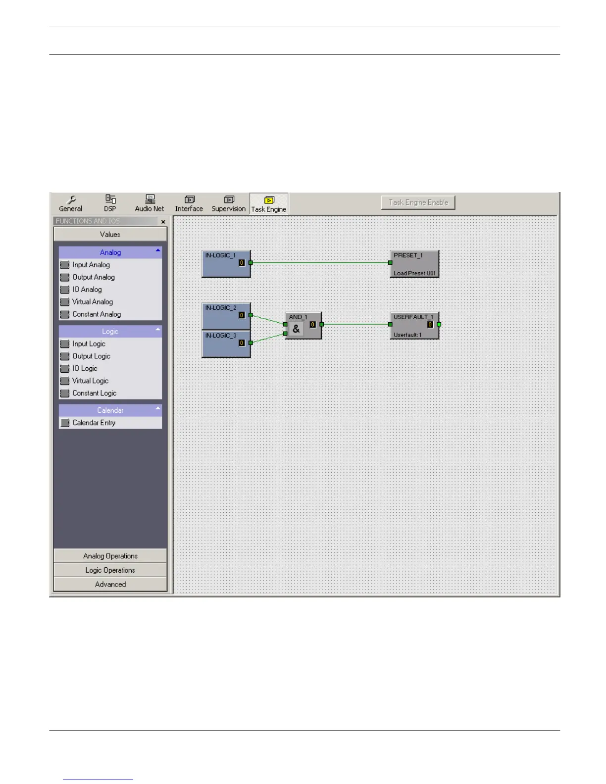
The Task Engine Window allows configuring the Task Engine by dragging inputs, links or outputs from the categories of
the FUNCTIONS AND IOS on the left corner of the screen into the Task Engine Worksheet. Elements can be freely
positioned and wired within the worksheet. Double-clicking on inputs or outputs allows configuring them in detail.
Building task engine configurations and changing the properties of task engine blocks is only possible in offline mode.
If any changes are made the new configuration must be 'sent' to the N8000 when going online. Please refer to section
“How to configure a Control” on page 20 how to assign functions and connections to a Task Engine block.
In the Task Engine, two classes of variables are available:
– Analog: variables of the type "analog" are rational numbers. Example: Level value (-80...+18) of a DSP block mono
mixer output.
– Logic: variables of the type "logic" are Boolean values, i.e. only the values "0" and "1" are allowed. Example: Mute
(0 = not muted, 1 = muted) of a DSP block mono mixer output.
In the Task Engine, different colors are used to distinguish the two types of variables. Analog blocks have blue
connection nodes and blue wiring connection lines. Logic blocks have green connection nodes and green wiring
connection lines. Connecting analog nodes to logic nodes is not allowed.
IRIS-Net DIGITAL MATRIX | en 333
Bosch Security Systems B.V. User Manual 2017.05 | 3.20 | F.01U.119.956