0.5 s 0.3...20 s GAIN DECREASE defines the time interval that it takes the AGC to
reduce the signal level to the TARGET.
0.05 s 0.05...60
s
HOLD defines how long the AGC keeps amplifying the signal after
the signal level has dropped out of the AGC’s operational range
(below the set THRESHOLD and KNEE level, which are relative to
TARGET).
1 s 0.3...20 s RELEASE defines the time that it takes to control the signal back to
unity gain after the HOLD period has passed.
0 dBu -6...+18
dBu
TARGET fader for setting the desired output level (average RMS
level) for the processed audio signal.
This field shows the currently set TARGET as a numerical value.
Entering the desired target value is possible as well.
BYPASS activates (not engaged) or deactivates (engaged) the AGC,
which allows quick A / B comparison between the original signal and
the signal after AGC processing.
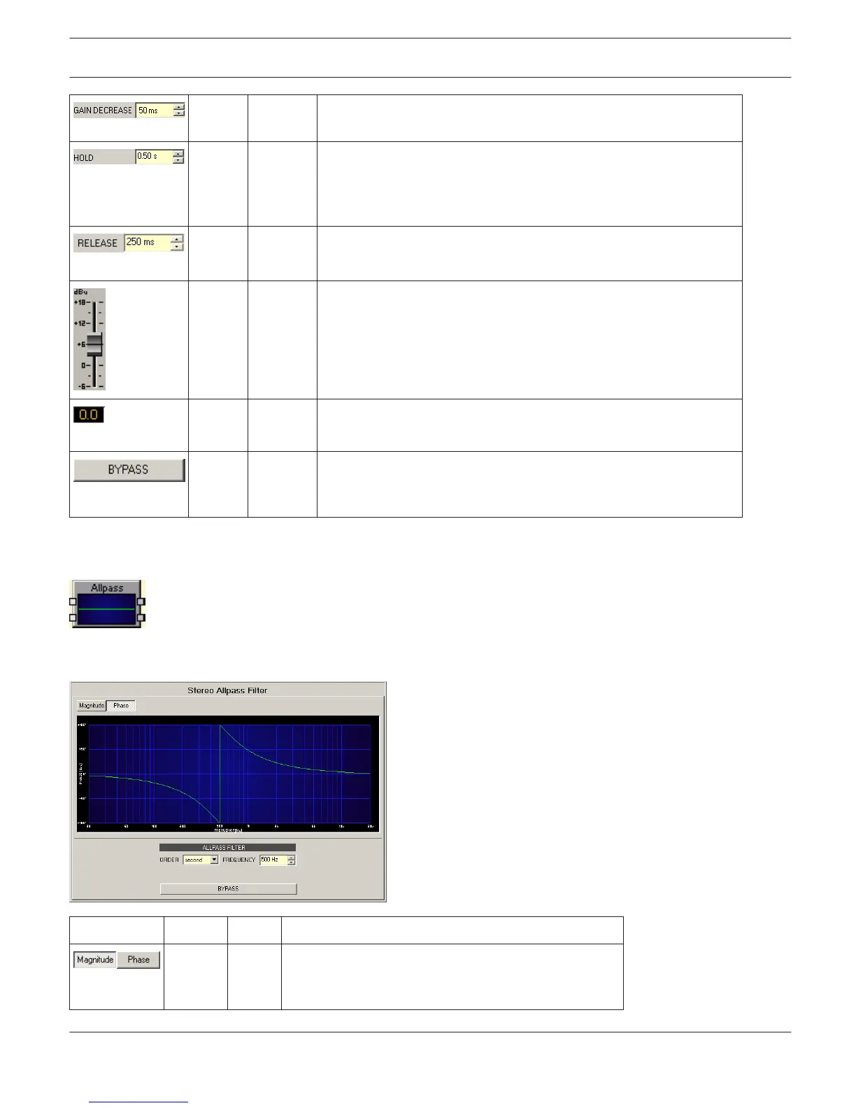
ALLPASS FILTER
When compared to other filter types, the All-Pass filter in the DSP block offers constant gain for all
frequencies. However, All-Pass filters have frequency-dependent phase shifting (non-linear phase response), which is
used for signal delay or phase equalization.
Element Default Range Description
Switch for selecting amplitude frequency response
(magnitude) or phase response (phase) indication in
the bode plot.
IRIS-Net DIGITAL MATRIX | en 369
Bosch Security Systems B.V. User Manual 2017.05 | 3.20 | F.01U.119.956