250 ms 50...999
ms
RELEASE defines the time it takes for limiter
to return to normal level after the signal level
declined the threshold.
BYPASS activates (not engaged) or
deactivates (engaged) the limiter, which
allows for quick A / B comparison between
limited and unlimited signals.
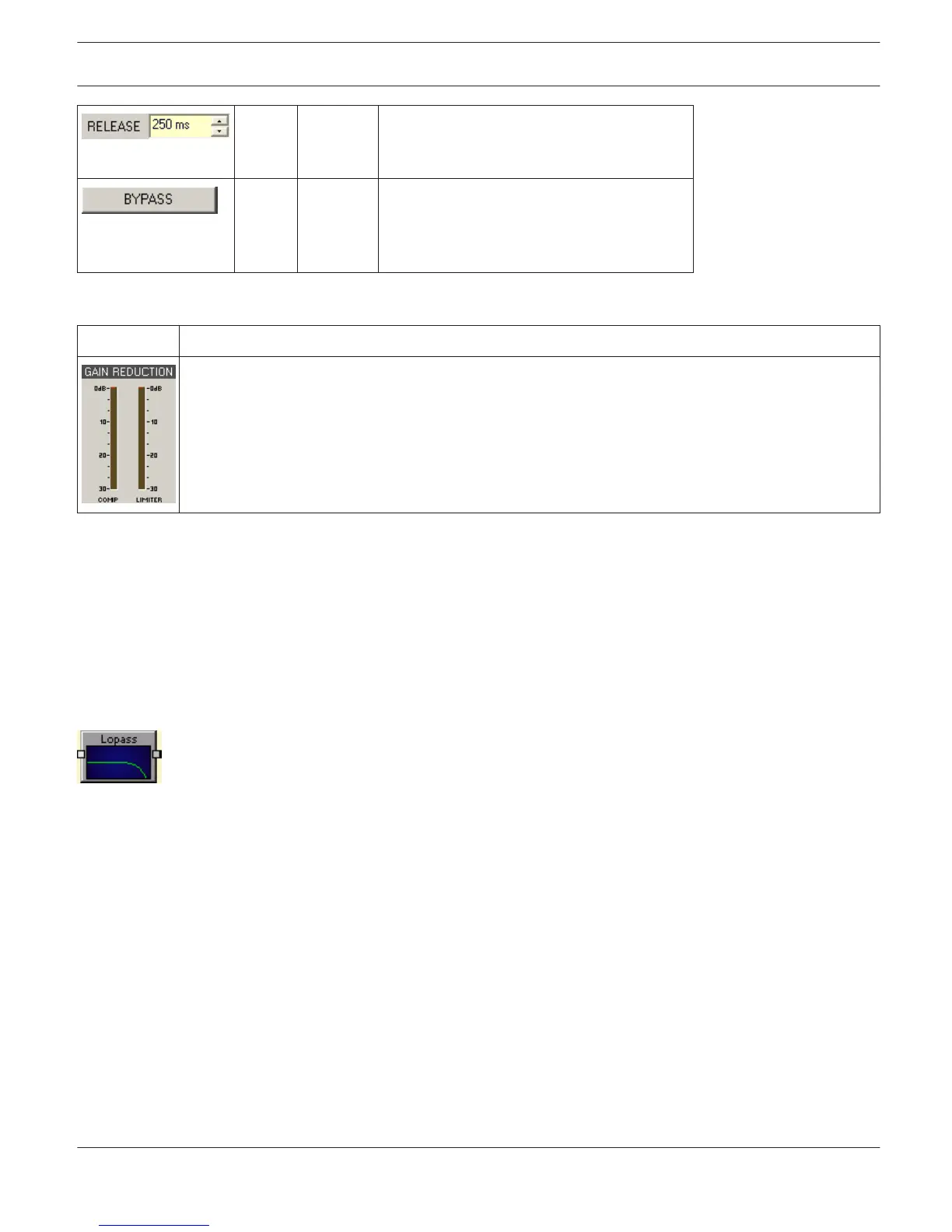
Meters
Element Description
These meters indicate signal reduction of the compressor (COMP) or limiter in dB. A yellow bar
increasing from top to the bottom indicates the degree of level reduction.
Editing Compressor / Limiter parameters via Mouse Dragging in the Graphic Display
If a compressor or limiter has been activated (Bypass is not engaged), the graphic display shows white dots that re-
present the according threshold values. Click onto one of these dots with the left mouse button and keep it pressed
down to set the threshold value of the corresponding compressor or limiter by dragging the mouse up or down. Click
with the right mouse button onto the compressors white dot and keep the mouse button pressed down to edit its
ratio.
LOW-PASS FILTER
Low-pass filters pass low frequencies and stop high frequencies. Since it is not realistically possible to
create a perfect filter that passes low frequencies totally unaltered and stops high frequencies completely, low-pass
filter design involves compromises that allow some rounding of the corner at the filter cutoff frequency and some slope
in the transition to the high frequency stop band. Different compromise schemes are given different names; examples
are Bessel, Butterworth and Linkwith-Riley lowpass filter types.
The cutoff frequency is defined as the frequency at which the magnitude of the filter response has fallen to -3 dB
relative to the unfiltered signal in the Bessel and Butterworth types, and to -6 dB in the Linkwitz-Riley types. The cutoff
frequency is continuously variable from 20 Hz to 20 kHz.
IRIS-Net
DIGITAL MATRIX | en 431
Bosch Security Systems B.V. User Manual 2017.05 | 3.20 | F.01U.119.956