– If input signals of different priority (>0) are assigned to different outputs, only the input signal with the highest
priority is connected through to the selected output(s). No signal is present at outputs that are only connected to
inputs with low priority, this means that set nodes of inputs with low priority are ignored in priority mode
"horizontal".
Setting connections is not restricted in any way, e.g. connecting various inputs to a single output as well as assigning a
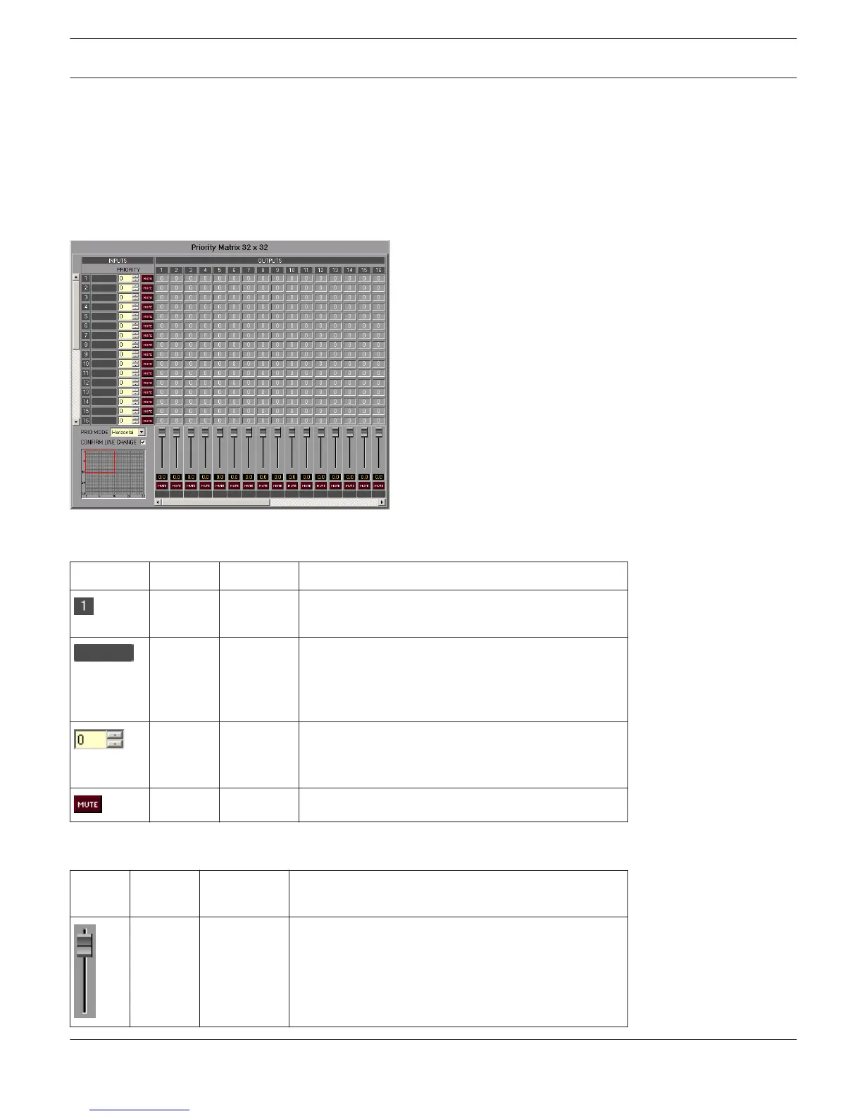
single input to a variety of outputs is possible. The notation I x O represents a matrix with I inputs and O outputs.
Inputs
Element
Default Range Description
Fixed channel labeling: channels are numbered from
1 to I.
Text field for providing an input channel with an
internal IRIS-Net name.
CAUTION: The use of * (asterisk) and = (equal) in
names is not permissible.
0 0...255 The Priority field shows the input channel’s set
priority. Entering the desired priority in the range
between 0 and 255 is possible.
MUTE button mutes the input signal.
Outputs
Elemen
t
Default Range Description
0 dB -80...0 dB Fader for setting the corresponding channel's output
level.
IRIS-Net DIGITAL MATRIX | en 445
Bosch Security Systems B.V. User Manual 2017.05 | 3.20 | F.01U.119.956