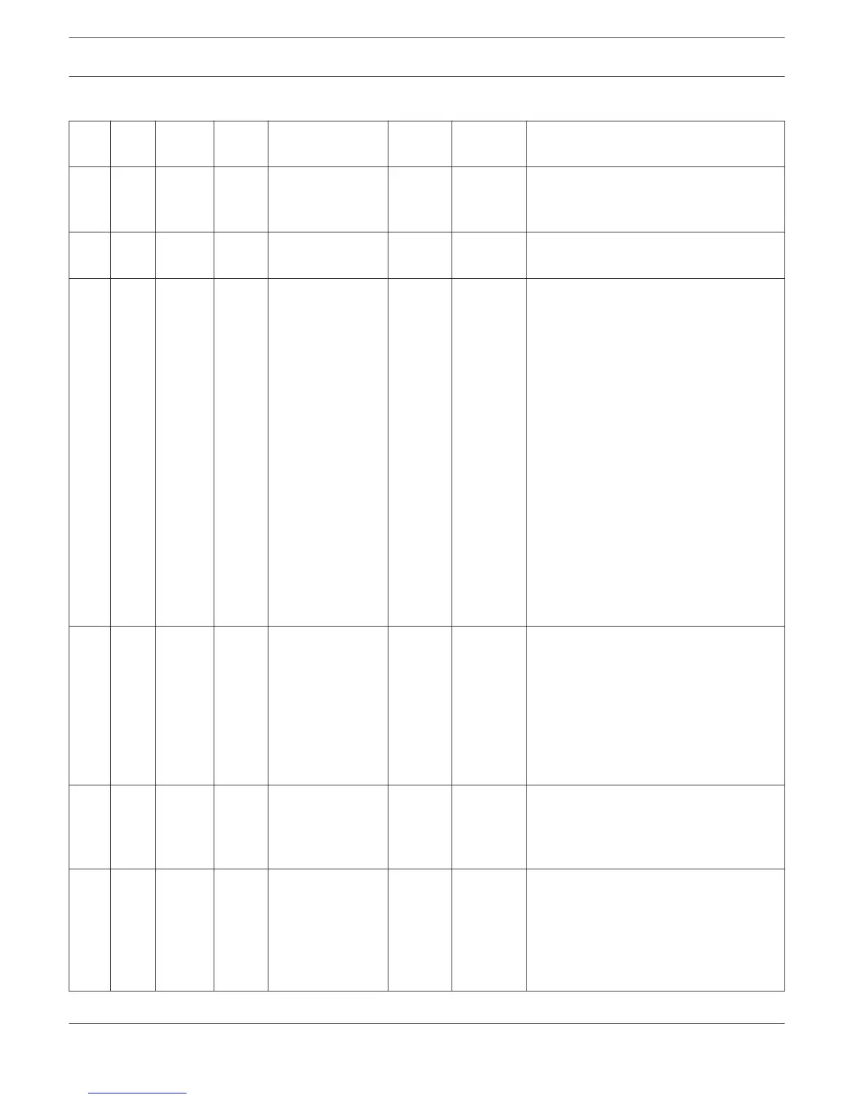
Commands for RCM-810
Read
Write
Values
Description
/
PARA
M
/AMP /
ADR1...
250
/
COMM
ON
/REVISION R Firmware version of RCM-810
/POWER R / W 0, 1 Switch amp ON / OFF or read out ON /
OFF state (0 = off, 1 = on)
/STATEFLAGS R 0x00...0xF
F,
0x00...0xF
F,
0x00...0xF
F,
0x00...0xF
F
32 Bit state flags of the amplifier in
hexadecimal format. 1: delayed power
switch
2: standby state
3: polling timeout from CAN master 4:
error in non volatile or tag memory 5:
collection result of local stateflags
6: global state of monitored collect
stateflags 7: overtemp (in any channel)
8 to 16 : unused
17: routing switch 'bridged' instead of
'normal' 18: mode switch 'parallel'
instead of 'dual'
19 to 21: unused
22: thermal shutdown flag from atmel 23
to 26: unused
27: mains voltage warning 28 to 32:
unused
/COLLECT R 0x00...0xF
F,
0x00...0xF
F,
0x00...0xF
F,
0x00...0xF
F
Bit mask for state flag selection in
hexadecimal format.
/GLBERR R 0x00...0xF
F,
0x00...0xF
F
Global error state of external can
devices, 1 bit per CAN device (1=error,
0=OK)
/GPISTATE R 0, 1 per
GPI
State of the two GPIs.
The value 0 means „not activated“, so the
input is open (high impedance). The
value 1 means „activated“, so the input is
connected (low impedance) to signal
earth.
IRIS-Net DIGITAL MATRIX | en 487
Bosch Security Systems B.V. User Manual 2017.05 | 3.20 | F.01U.119.956




 To Next Page