The Output FIR is selected by clicking on the tenth block (FIR) of the flow diagram selector or on the SPEAKER PRO-
CESSING FIR block in the full-scale flow diagram.
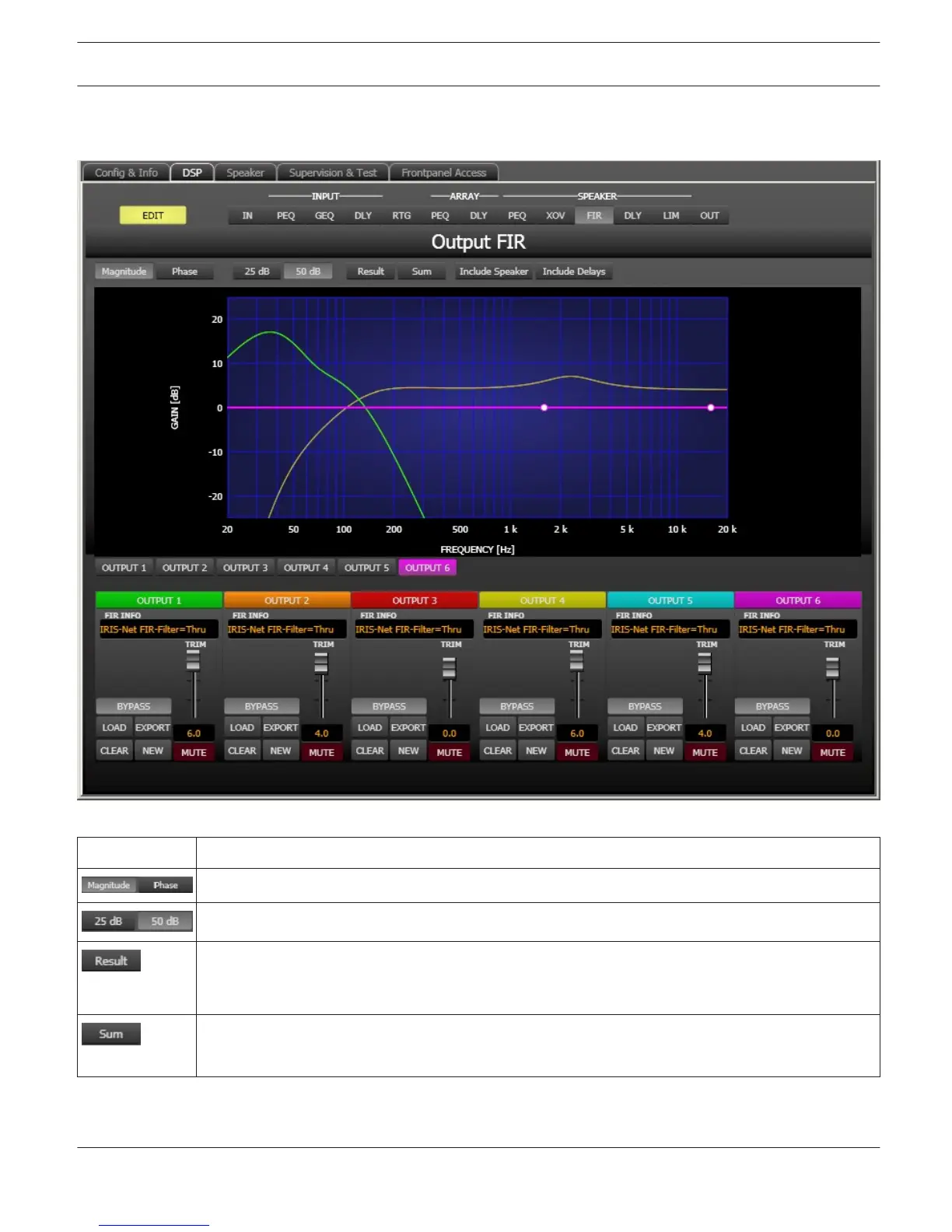
Element Description
Switch for displaying frequency response (magnitude) or phase response (phase)
Switch for scaling the dB-axis to 25 dB (± 12.5 dB) or to 50 dB (± 25 dB)
Displays the resulting transfer function of all filter and level trim settings and therefore graphically
displaying the audible result at the sound system processor outputs. The audible result is displayed
in bright colors while all ”electrical” graphs are drawn in dark colors.
The ”Sum” switch causes display of the summed signal of the output channels. If the ”Sum ” switch
is not pressed the output channels’ transfer functions are indicated separately.
IRIS-Net DIGITAL SOUND PROCESSOR | en 636
Bosch Security Systems B.V. User Manual 2017.05 | 3.20 | F.01U.119.956