100
ELECTRICAL AND IGNITION
ELECTRIC START CIRCUIT
Start Circuit Operation
The st arter must engag e and tu rn the flywhee l.
The outboard must crank a minimum of 100 RPM
to st art. Normal cranking speed is approximately
175 RPM.
Starter performance depends on the following:
• Proper battery and cable capacity.
• Clean, tight cable connections.
• Solenoid activation through the key switch, neu-
tral safety switch, and EMM.
Refer to Predelivery and Installation Guide for
battery, terminal, and cable requirements.
Solenoid Wiring
The positive (B+) battery cable connects to a large
terminal of the starter solenoid. This terminal also
provides the 12 V power supply to the engine har-
ness (red wire) and the 10 A fuse. The red/purple
wire from the fuse holder (10 A) provides 12 V to
terminal “B” of key switch.
The negative (B–) batte ry ca ble co nnects to the
main ground stud next to starter solenoid.
Engine Wire Harness
Contains the following circuits:
• Red/purple output wire from fuse provides 12 V
to instrument harness.
• Purple wire p rovides switched 12 V to so lenoid
(terminal “A”) and EMM.
• Yellow/red wire provides switched 12 V to EMM.
• Brown/white wire from terminal 11 of EMM J1-B
connector pro vides switche d ground (NEG) to
starter solenoid (terminal “B”).
Instrument Wire Harness
Contains the following circuits:
• Red/purple wire provides 12 V to key switch ter-
minal “B”.
• Purple wire pro vides switch ed 12 V to engine
wire harness.
• Yellow/red wire from terminal “S” of key switch
provides swit ched 12 V to EMM (key sw itch in
START position).
Key Switch, ON position
12 V is ap plied to the accessory circuit. Key
switch ON:
• Switches 12 V to terminal “A” of key switch and
to the purple wires of the wire harnesses.
• Provides 12 V input to terminal 21 of EMM J1-B
connector. EMM turns ON.
• EMM provide s 12 V to terminal “A” of st arter
solenoid.
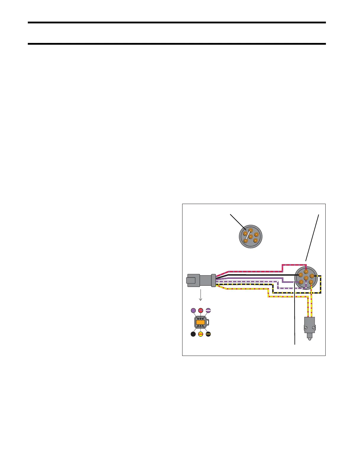
1. Key switch, ON position – Continuity between ter-
minals “B” and “A”
2. Terminal “B”, 12 V (Red/purple)
3. Terminal “A”, 12 V (Purple)
000691
B
M
M
C
A
S
M
B
S
A
C
M
M
B
S
A
C
M
M
B
S
A
C
M
456
123