174
OILING SYSTEM
OILING SYSTEM TESTS
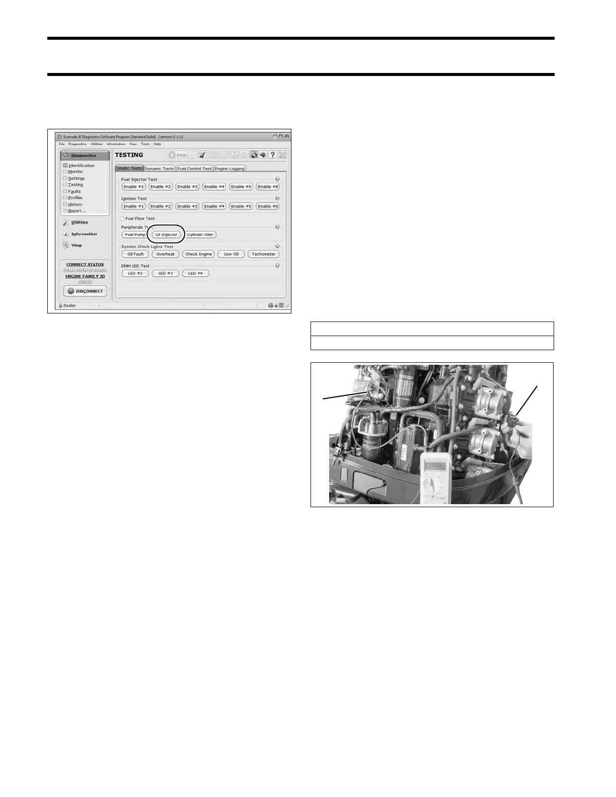
Use the Oil Injector te st o f Evinrude Diagnostic
software Static Test screen to activate the oil
pump.
Observe voltage at pin 2.
• Voltage at pin 2 should drop as the oil pump
cycles.
Check the control signal while the Oil Injector test
is running. Set the digit al multimeter to the Hertz
(Hz) scale.
• Meter should read approximately 10 Hz.
Results:
• If volt age and co ntrol sign al rea dings at pin 2
are within range, the EMM and wiring are not at
fault.
• If voltage at pin 2 is not within range, check volt-
age at pin 1 (white/red wire) of oil pump electri-
cal connector.
Connect positive meter lead to pin 1 (white/red
wire) of oil injectio n pu mp electrical connector.
Observe voltage at pin 1.
• Voltage at pin 1 should be approximately 30 V.
Start the engine. Observe voltage at pin 1.
• The volt age at pin 1 sh ould be appro ximately
55 V.
• If voltage is not within range, refer to Oil Injec-
tion Pump Circuit Resistance Test on p. 174.
• No volt age reading, refe r to System V oltage
Test on p. 81.
Oil Injection Pump Circuit
Resistance Test
IMPORTANT: The complete oil injection pump
electrical circu it includes EMM alternator outp ut,
the engine wire harness, the injection pump wind-
ing and connectors, and the oil injector control cir-
cuit of the EMM. Check continuity of all wiring and
connections.
Disconnect the battery cables at the battery.
Disconnect J1-B connector from EMM. Use a digi-
tal mu ltimeter with appropriate adap ter leads to
measure the resist ance between pin 23 (blu e) of
the EMM J1-B connector a nd pin 1 (white/red) of
the oil inje ction p ump connector. Calibrate t he
meter to the LOW OHMS scale.
• An infinite reading (∞) indicates an open circuit.
Isolate the fa ulty com ponent. Check continuity
of wiring, con nections, or inje ction pump win d-
ing. Repair faulty wiring or replace faulty pump.
• For a higher t han expected reading, test resis-
tance of the inject ion pump. If injection pump
resistance reading is within rang e, inje ction
pump winding is good. Isolate faulty compo-
nent. Repair faulty wiring or replace faulty com-
ponent and retest.
Static Tests Screen 008569
Oil Injection Pump Circuit Resistance
2 to 3 Ω
1. EMM J1-B connector (pin 23)
2. Oil injection pump connector (pin 1)
004343