240
POWERHEAD
POWERHEAD ASSEMBLY
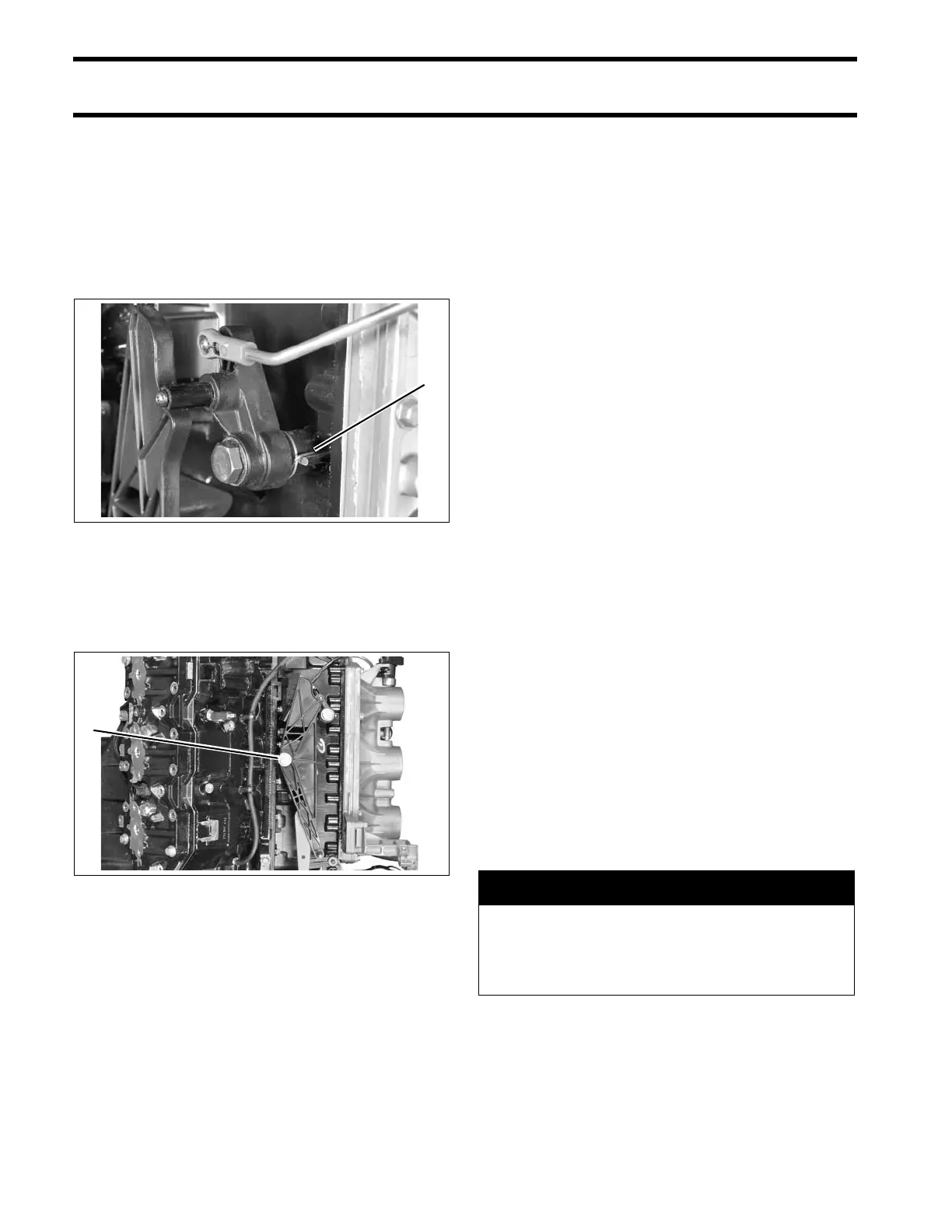
Throttle Linkage Installation
Apply Nut Lock to threads of throttle lever screw.
Insert spring into cavity of throttle lever.
Install lever, screw, and washer on crankcase and
hook spring on r ib as sh own. Tighten screw t o a
torque of 120 to 144 in. lbs. (13.5 to 16.5 N·m).
Apply Nut Lock to threa ds of throttle cam screw.
Install cam, scre w, and washer on cylinder b lock
and tighten screw to a torque of 120 to 144 in. lbs.
(13.5 to 16.5 N·m).
IMPORTANT: Do not lubricate throttle levers or
shoulder screws.
Final Powerhead Assembly
Install the reed plate and throttle body assemblies.
Refer to Intake Manifold Service on p. 151.
Install oil recirculatin g hoses and che ck valves.
Refer to OIL RECIRC ULATION DIAGRAMS on
p. 162, or POWERHEAD VIEWS on p. 244.
Install pressure valve assemb ly. Re fer to PRES-
SURE RELIEF VALVE SERVICING on p. 193.
Install shift linkage. Refer to Shift Linkage Instal-
lation on p. 239.
Install throttle linkage. Refer to Throttle Linkage
Installation on p. 240.
Install fue l injecto rs and ignition coils. Ref er to
Fuel Injector Installation on p. 149.
IMPORTANT: All injectors must be reinstalled in
their original location. Improper injector installation
can result in powerhead failure.
Install oil pump, rear oil manifold, and oil injection
hoses. Ref er to OIL COMPONENT SER VICING
on p. 178.
Install stator. Refer to Stator Service on p. 109.
Install electrical harness and EMM. Refer to EMM
SERVICING on p. 70.
Install fu el pump assemblies, fuel man ifolds, and
filter. Refer to FUEL COMPONENT SER VICING
on p. 143.
Install the electric starter. Refer to Starter Instal-
lation on p. 121.
1. Throttle lever spring 006966
1. Throttle cam screw 006866
A WARNING
To preve nt fire an d expl osion hazard,
make sure all electrical and ignition wiring
is routed and clampe d in original posi-
tions.