108
ELECTRICAL AND IGNITION
TACHOMETER CIRCUIT TESTS
LOW OIL Circuit Test
Turn the key switch ON. Using a jumper wire, con-
nect tan/black wire (pin 4) of the engine harness
connector to a clean en gine ground. The LOW
OIL light should turn on after 40 seconds.
If the LOW OIL ligh t does not turn on af ter con-
necting the terminal to ground, test circuit for con-
tinuity.
Turn the key switch OFF and reconnect all discon-
nected circuits.
NO OIL Circuit
Separate th e 6 -pin SystemCheck connector of
MWS instrument harness from engine harness.
Black wire (pin 3) must be grounded.
Using a jumper wire, connect tan/yellow wire (p in
5) to a clean engine ground.
Turn the key switch ON. After the normal self-test
sequence, the NO OIL light should stay on.
• If the NO OIL light is not on, test circuit for conti-
nuity. Test for continuity of the MWS instrument
harness (tan/yellow wire).
• Test for continuity of the eng ine wire harness
between terminal 5 (tan/yellow wire) of the Sys-
temCheck connector and pin 24 of the EMM J1-
A connector.
Turn the key switch OFF and reconnect all discon-
nected circuits.
TACHOMETER CIRCUIT
TESTS
Check voltage at the battery. Use this reading as a
reference for battery voltage.
Connect the red meter lead to the tachometer pur-
ple wire and the black meter lead to the tachome-
ter black wire (key ON, outboard NOT running).
• If meter shows battery voltage, go to next step.
• If meter shows less than battery voltage, check
the purple, red/purple, and black wiring circuit s;
fuse, key switch, and battery connections.
Disconnect g ray a nd black wires at t achometer.
Set Fluke 29 Serie s II mete r, or equivalent, to Hz
scale. Co nnect mete r between gra y wire a nd
black wire. With outboa rd running at 100 0 RPM,
meter should indicate 90 to 105 Hz.
• If meter read s 90 to 1 05 Hz, replace tachome-
ter.
• If meter reads low or no signal, confirm outp ut
on gray wire at pin 16 of EMM J1-A connector.
– Reading OK – Check condition of tachometer
circuit (gray wire). Repair as needed.
– Reading not OK – Check connection at EMM;
replace faulty EMM.
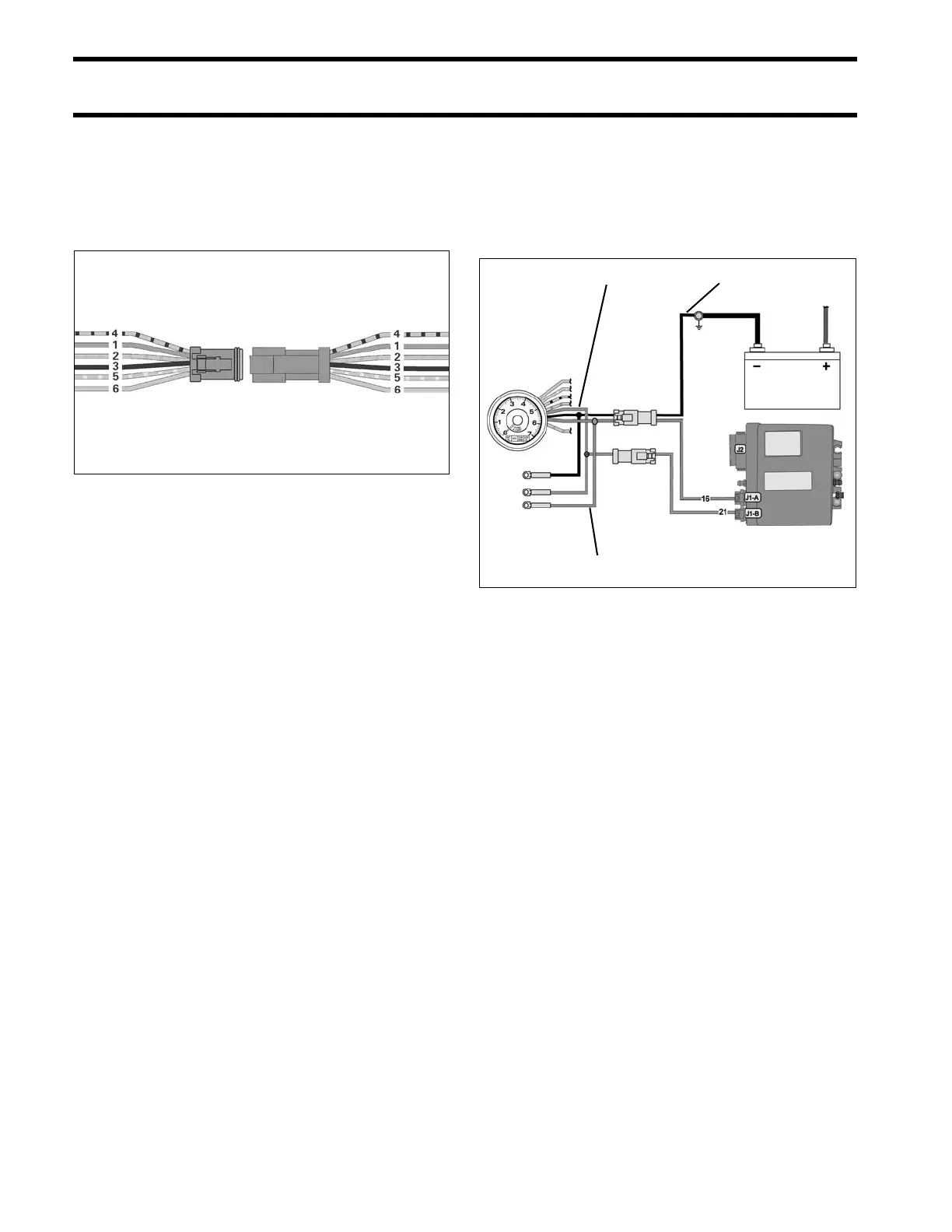
002079
1. Purple lead
2. Black lead
3. Gray lead
004287