204
EVINRUDE ICON REMOTE CONTROL SYSTEM
ICON COMPONENT SERVICING
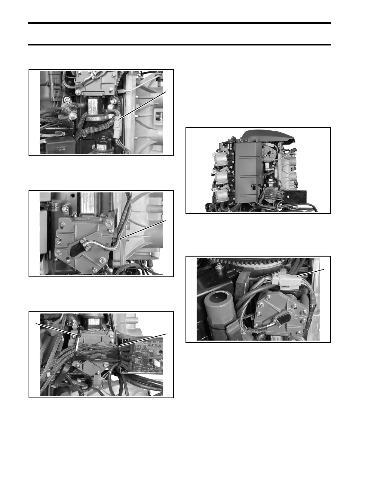
Connect the shif t actuator harne ss. Attach to clip
on mounting plate.
Secure sh ift actua tor harne ss wit h tie st rap,
P/N 317893.
Route all ESM harnesses as shown and secure to
shift actuator with tie straps, P/N 907833.
IMPORTANT: Do not install shif t link unt il the
calibration procedure has been completed. Refer
to Calibrate Actuator Stroke on p. 207.
Throttle Actuator
Removal
Disconnect the battery cables at the battery.
Remove the flywheel cover. Remove the electrical
bracket cover.
Observe and note all wire routings before disas-
sembling.
Remove th e thrott le actuato r conn ector from t he
clip on the mounting plate. Disconnect the throttle
actuator harness.
1. ESM to shift actuator harness 007498
1. Shift harness tie strap 007872
1. Large tie straps 008508
007525
1. Throttle actuator connector 007497