84
SYSTEM ANALYSIS
IGNITION OUTPUT TESTS
Ignition Control Circuit Tests
Use a digital multimeter to test the following:
• System voltage supply to ignition coil.
• Ignition control signal from EMM.
• Engine harness resistance.
Disconnect ignition coil connector.
Supply voltage test:
Use an ap propriate adapter to connect the red
meter lead to pin 3 (wh ite/red) of the engine har-
ness connector and the black lead to ground. With
EMM ON, voltage should be approximately 30 V.
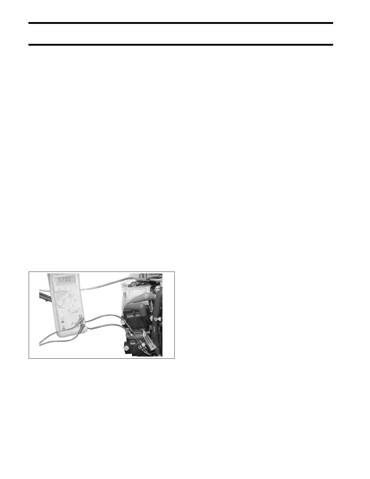
Control signal test:
Set meter to the Hz scale to check ignition control
signal.
Use an ap propriate adapter to connect the red
meter lead to pin 2 (orange) of the engine harness
connector and th e black le ad to ground. Activate
diagnostics sof tware Static Ignition test and
observe me ter for consist ent read ing (a pproxi-
mately 2 Hz).
If control signal is present, connect bla ck meter
lead to p in 1 (black) and re peat te st to confirm
harness ground.
Harness resistance test:
If control signal is NOT present, calibrate multime-
ter to low ohms scale . Use appro priate adapte rs
on mete r leads to avoid dama ging harness con-
nectors.
With EMM OFF, remove the EMM J1-B connector
and test the continuity of each ignition control cir-
cuit (orange). Check resistance bet ween J1-B
connector an d ig nition coil connector. Refer to
engine wiring diagram.
If circuits test good, replace EMM.
Ignition Coil Tests
There are no simple ignition coil test s available.
Before replacing an ignition coil, be sure:
• 55 V is supplied to the white/red wire of the igni-
tion coil connector
• A control signal is present on the orange wire of
the ignition coil conn ector. Re fer to Ignition
Control Circuit Tests on p. 84.
• The black wire of the ignition coil connector pro-
vides continuity to ground.
• The secondary sp ark plug le ad provides cont i-
nuity.
If all of the above tests a re g ood, and a cylinder
does not have spark, replace the ignition coil with
a known good coil.
Capacitor Test
IMPORTANT: Make sure the ca pacitor is dis -
charged before testing. Ma ke a mo mentary co n-
nection between the two terminals to ground any
stored energy.
Remove capacitor from electrical harness.
Use an ohmmeter set on the high ohms scale to
test the capacitor. Connect the meter leads to t he
capacitor terminals:
• If the capacitor is working co rrectly, it will sto re
energy from the meter. The resist ance reading
will increase until it goes to (nearly) infinity.
• If th e ca pacitor is shorted, the reading will
immediately show full continuity.
• If there is an open circuit in the ca pacitor, the
meter will show no continuity.
If the resistance reading starts as a negative num-
ber, or the reading goes down in value, the capac-
itor already ret ains some sto red e nergy. Ground
the capacitor and test again.
006609