142
FUEL SYSTEM
FUEL SYSTEM TESTS
Results:
Normal pressure
• Perform the Lift Pump Vacuum Test on p. 142.
Make sure no a ir lea ks or restrictions ex ist in
the fuel supply hose or boat fuel system.
Low pressure
• Check pulse hoses and fittings for restrictions.
• Perform the Lift Pump Vacuum Test on p. 142.
Make sure no a ir lea ks or restrictions ex ist in
the fuel supply hose or boat fuel system.
• Check fuel flow through fuel lift pump. Use fu el
primer bulb to force fuel through pump.
No pressure
• Check pulse hoses and fittings restrictions.
• Check fuel flow through fuel lift pump. Use fu el
primer o r primer bulb to force fu el throu gh
pump.
• Momentarily prime or squee ze p rimer bulb to
check gauge operation.
• Check pulse hose and fittings for restrictions.
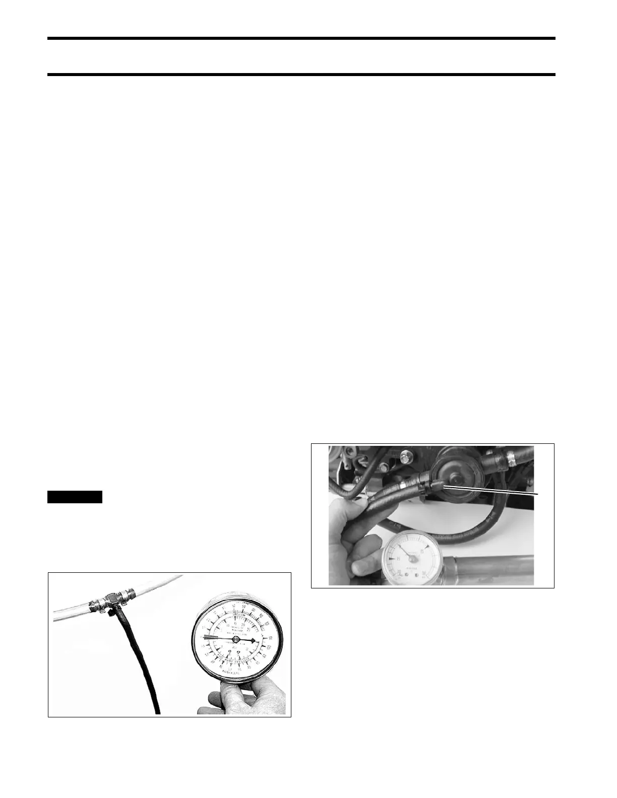
Lift Pump Vacuum Test
Confirm fuel supply to the fuel lift pump.
Temporarily install a vacu um gauge, T-fitting, and
8 in. (20.3 cm) of clear vinyl hose between the fuel
supply hose and fuel lift pump (inlet). Secure con-
nections with tie straps to prevent fuel or air leaks.
Do not use fuel primer bulb, manual
fuel primer, or ele ctric fuel pump primer to
restart o utboard. A posit ive pressu re in the
fuel suppl y could dama ge som e vac uum
gauges.
START outboard and run at FULL THROTTLE for
at least two minutes. Monitor clear vinyl ho se for
the presence of air . Air bubbles ind icate a faulty
hose, connection, o r f uel tank p ick-up. Repair, if
necessary, before proceeding.
There should be no air or vapor bubbles visible in
the clear hose. The maximum inlet fuel va cuum
should not exceed 4 in. Hg. (13.5 kPa) at the inlet
to the fuel lif t pu mp under any o perating cond i-
tions (IDLE to WOT).
A higher vacuum indicate s an excessive restric-
tion in the fuel supply. Repair as needed. Refer to
FUEL SYSTEM REQUIREMENTS on p. 133 for
fuel supply component requirements.
Lift Pump Diaphragm Test
Perform this test only if a damaged pump is sus-
pected. This test does not check the performance
of internal fuel pump check valves.
Remove both pulse hoses from the crankcase fit-
tings.
Apply 15 psi (103 kPa) to each of the pulse hoses
of the pu mp. Replace lif t pu mp if either side of
pump fails to hold pressure.
000243
1. Pulse fitting 000670