241
POWERHEAD
POWERHEAD INSTALLATION
11
POWERHEAD
INSTALLATION
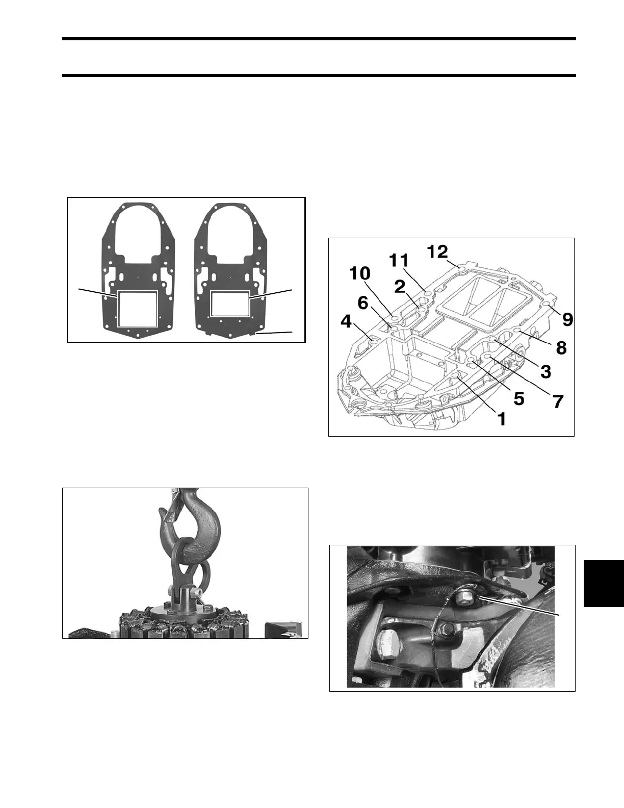
Apply Permatex No. 2 to both sides of a new base
gasket around the exhaust port only. Install gasket
on adapter. To ensure proper sealing, mating sur-
faces must be clean and dry.
Coat the driveshaft splines with Moly Lube. Do not
apply lubricant to end of driveshaft.
Use Lif ting F ixture, P/N 396748, an d hoist to
slowly lower p owerhead ont o exhaust h ousing. If
necessary, rotate flywheel in a clockwise direction
to align crankshaft and driveshaft splines.
Apply Gasket Sealing Compound to the threads of
all powerhead screws.
Loosely install all fasteners before tightening.
Tighten the 3/8 in. diameter powerhead screws to
a torque of 20 to 22 ft. lbs. (27 to 30 N·m) in the
sequence shown.
Tighten t he 5/1 6 in. diamet er powerh ead screws
to a torque of 144 to 168 in. lbs. (16.5 to 19 N·m)
in the sequence shown.
IMPORTANT: Retighten powerhea d mo unting
screws after outboard has been run at full operat-
ing temperature and allowed to cool.
Install two fro nt and o ne rear po werhead nu ts.
Tighten nuts 144 to 168 in. lbs. (16.5 to 19 N·m).
Crankcase to Adaptor Gaskets
1. Exhaust port area – 3.3 L models
2. Exhaust port area – 3.4 L models
3. Identification tab (3.4 L models only)
008324
48758
004261
1. Front powerhead nut (2) 004262