239
POWERHEAD
POWERHEAD ASSEMBLY
11
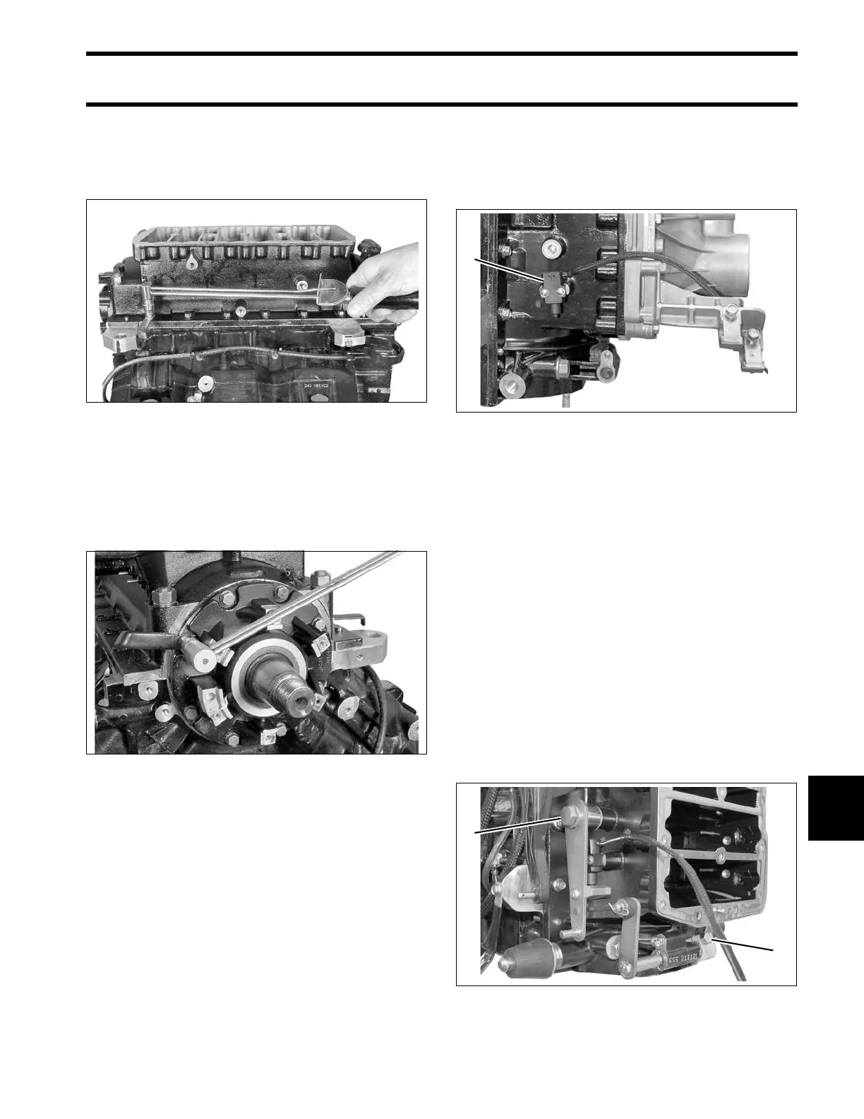
Apply Permatex No. 2 to crankcase flange screws
where thre aded hole is op en to crankcase .Install
screws and tighten to a torque of 84 to 108 in. lbs.
(9.5 to 12 N·m).
Test that the crankshaft spins freely without bind-
ing.
Apply Nut Lock to the upper and lower crankcase
head screws. Install and tight en screws t o a
torque of 96 to 120 in. lbs. (11 to 13.5 N·m).
IMPORTANT: After powerhead ha s be en
assembled, allow at least two hours for Gel-Seal II
to cure before running outboard.
Shift Linkage Installation
Install Neut ral/Shift In terrupt switch. Apply Nut
Lock to screw threads and tighten to a torque of 7
to 10 in. lbs. (0.8 to 1.1 N·m).
If removed , install cam on shif t arm. Apply Ultra
Lock to screw threa ds and tighten to a torqu e of
60 to 84 in. lbs. (7 to 9.5 N·m).
Lubricate sh ift linkage bosses a t the base of th e
crankcase with Triple-Guard grease. Inse rt bush-
ings into bosses.
Apply Triple-Guard grease to the shaft of the shift
lever assembly. Guide shaft through bushings in
crankcase.
Install shif t rod le ver an d tight en ret aining screw
60 to 84 in. lbs. (7 to 9.5 N·m).
Apply Triple-Guard grease to shoulder of shift arm
screw and Nut Lock to threads. Install arm, screw,
and washer a nd tighten screw to a torque of 120
to 144 in. lbs. (13.5 to 16.5 N·m).
004138
004142
1. Neutral/Shift Interrupt switch 008451
1. Shoulder screw
2. Shift rod lever retaining screw
008455