54
ENGINE MANAGEMENT MODULE (EMM)
DESCRIPTION
DESCRIPTION
The Engine Manage ment Mo dule (EMM) is a
water-cooled e ngine controller . It contro ls many
outboard systems in cluding alternato r ou tput for
the 12 V and 55 V circuit s. Operating vo ltage is
supplied to the EMM by the stator.
This section discusses the functio ns of the EMM
and it s variou s in ternal and externa l sen sors. It
also de scribes using Evinrude Diagnostics sof t-
ware to retr ieve and adjust service information
saved in the EMM
EMM Functions
The EMM co ntrols the following pro cesses and
functions:
• Alternator output; 55 V and 12 V
• Start Assist Circuit (SAC) voltage boost
• Fuel and ignition timing and duration
• Fuel injector activation
• Oil injector pump activation
• Electric fuel pump control
• Idle speed control
• RPM limiter
• Electrical circuit monitoring
• Service code creation and storage
• Warning system activation
• ROM verification, self-test
• Choke-less cold starting
• Output of diagnostic data
• Tachometer signal
• RPM profile and engine hours
• Oiling ratios
• Shift interrupt function
• Anti-knock compensation
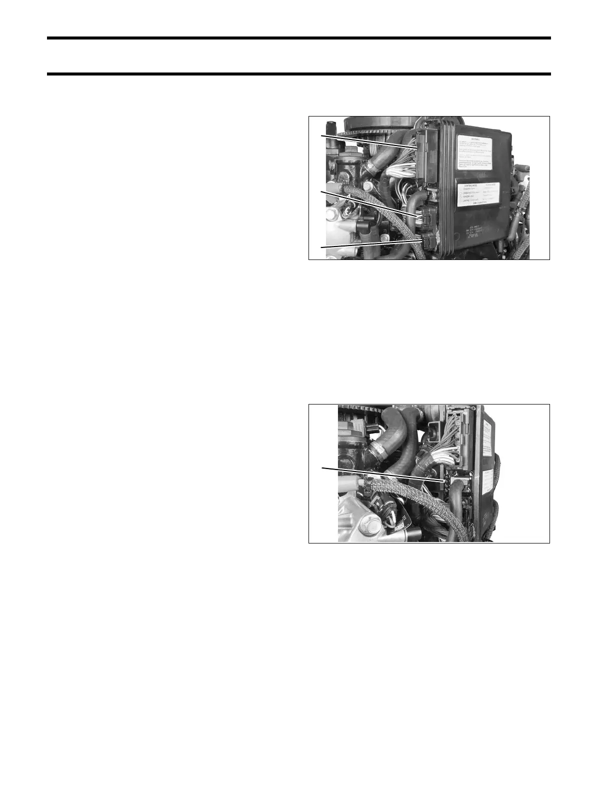
EMM Connections
IMPORTANT: EMM connections an d wiring
must be clean and tigh t. Improper ele ctrical con-
nections can damage the EMM. DO NOT r un the
outboard with loose or disconnected wiring.
Make sure EMM connections are clean and tight.
• Engine wire harness to EMM connectors; J1-A,
J1-B, J2
• Stator t o EMM connections; one 6-pin AMP and
J2 connector.
LED Indicators
The EMM has LED indicato rs located next to the
electrical conn ectors that pro vide informatio n
related to various electrical circuits.
IMPORTANT: LED 1 is to ward the top of t he
outboard (Closest to EMM J2 connector).
When the ignition key is turned ON, LEDs 1, 3 and
4 should light, indicating that the SAC circuit, sen-
sor circuits, and the stop circuit are working.
As the outbo ard is being started, all four LEDs
should light and then go off in sequence. If any of
the LEDs d oes NOT light during st arting, refer to
EMM LED INDICATORS on p. 78.
When the outboard is running, all LEDs should be
off. If any LED is lighted while the outboard is run-
ning, refer to EMM LED INDICATORS on p. 78.
1. J2 connector
2. J1-A connector
3. J1-B connector
004197
1. LED indicators 004198