97
ELECTRICAL AND IGNITION
CHARGING SYSTEM TESTS
6
CHARGING SYSTEM
TESTS
12 V Charging Circuit
To test the operation of the regulator in the EMM,
you must be able to run the outboard continuously
at approximately 5000 RPM, such as in a test tank
or on a marine dynamometer.
The test consist s of monito ring th e system’ s
response to a partially disch arged battery. Use a
variable load tester to discharge the battery.
IMPORTANT: The regulator req uires voltage to
operate. Before proceeding, make sure there is at
least 7 V on t he positive t erminal o f the st arter
solenoid.
Disconnect the battery cables at the battery.
Use an inductive amp meter or connect a 0 to
50 A ammeter in series between the red wire(s) of
engine wire harness (alternator output from EMM)
and th e p ositive (B+) battery cable te rminal of
starter solenoid.
IMPORTANT: This outboard has dual out put
charging. Each ou tput is isolated and regulated.
Each output is 25 A. Combined output is a pproxi-
mately 50 A. Refer to engine wiring diagram.
Fluke
†
model 334 or 336, Snap-On
†
model MT110
or EETA501, an d various o ther a mp meters
should be available through local tool suppliers.
Reconnect the battery cables.
Following the manufa cturer’s dire ctions, conne ct
the variable lo ad teste r (carbon pile) across the
battery terminals. Stevens mo del LB-85 a nd
Snap-On model MT540D are examples o f testers
available.
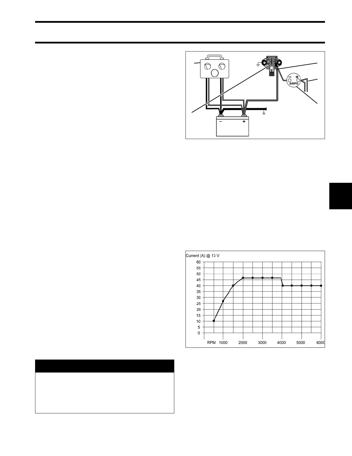
Start and run th e outboard at approximately 3500
RPM. Use the variable load tester to draw the bat-
tery down at a rate equivalent to the stator’s full
output.
• The ammeter should indicate nearly full output,
approximately 50 A (or 25 A for each outp ut)
between 2000 and 4000 RPM.
• Above 4000 RPM, charging output is reduced to
40 A.
Decrease the battery load toward 0 A.
• Ammeter should show a reduced output. As the
current draw decreases, th e battery volt age
should stabilize at approximately 14.5 V.
• If results vary, check stator BEFORE replacing
the EMM. See STATOR TESTS on p. 96.
A WARNING
Excessive battery disch arge rates might
overheat battery causi ng electrolyte gas -
sing. This might create an explosive atmo-
sphere. Alway s work in a well v entilated
area.
Variable Load Test Diagram
1. Red wires (alternator output from EMM)
2. Starter solenoid
3. Battery cable terminal (B+)
4. Variable load tester
5. Ammeter
002077
Battery Charging Graph 004286