295
GEARCASE
SHIFT ROD ADJUSTMENT
13
On 25 in. and 30 in. models, place the appropriate
water tube sp acer and grommet on the impeller
housing cover.
After water pump is assemble d completely, rotate
driveshaft cou nter clockwise 1/4 turn to un lock
and release impeller and key from driveshaft.
Next, pull up on d riveshaft a nd tu rn clockwise to
lock impe ller to shaf t. This process increases
pump efficiency by lockin g the impeller lower on
the driveshaft.
Before installing gearcase, shift rod
adjustment MUST be checked. Refer t o SHIFT
ROD ADJUSTMENT on p. 295.
SHIFT ROD
ADJUSTMENT
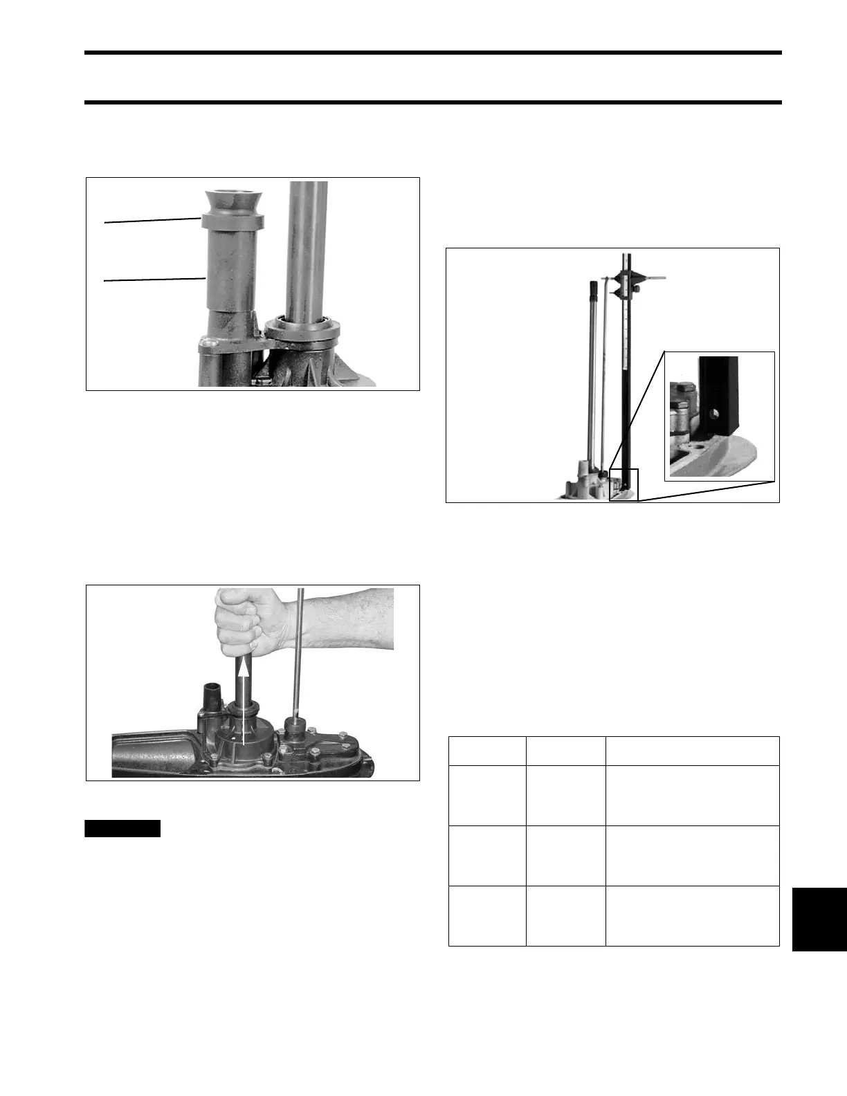
Check the shift rod height from the shift rod hole to
the surface of the gea rcase using Universa l Shift
Rod Height Gauge, P/N 389997.
With the gea rcase in NEUTRAL , rot ate the shif t
rod up or d own as necessary fo r cor rect a djust-
ment. Once correct height is achieved, rotate rod
one half turn or less to direct offset forward.
IMPORTANT: The NEUTRAL dete nt is a two-
step design. Make sure the NEUTRAL detent ball
is in the ce nter step before ch ecking sh ift rod
height.
Shift Rod Heights
1. Spacer
2. Grommet
32728
007078
COA6166
Model Type Height
20 in. (L)
“L2”
“M2”
21 29/32 in.
(21.906 in./ 556 mm)
± 1/2 Half Turn
25 in. (X)
“L2”
“M2”
26 29/32 in.
(26.906 in./ 683 mm)
± 1/2 Turn
30 in. (Z) “M2”
31 29/32 in.
(31.906 in./ 810 mm)
± 1/2 Turn