335
TRIM AND TILT
MODES OF OPERATION
14
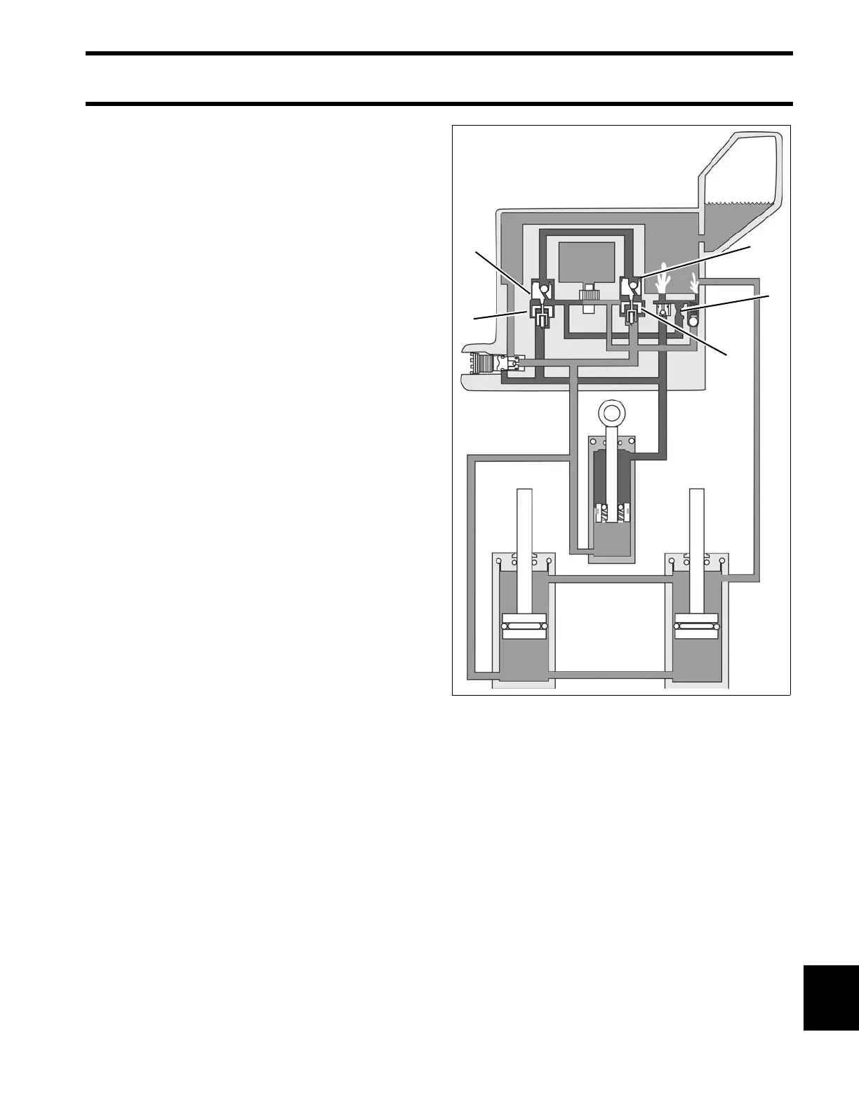
Tilt-DOWN / Trim-IN Mode
When the DOWN switch is pressed, t he trim/tilt
motor rot ates counterclockwise (as viewed from
pump end) and turns the pump gears.
Fluid pressure passes through the DOWN shuttle
valve to the UP shuttle valve, which mechanically
opens the UP check valve.
Fluid pressure pushes t he DOWN check valve o ff
its seat and fluid passes through the valve to the
top of the tilt cylind er, mo ving the tilt piston
DOWN.
When the swivel bracket con tacts the top of the
trim rods, the mecha nical force of the tilt cylin der
pulling th e ou tboard down also pu shes th e trim
pistons down. Fluid is pulled from the reservoir to
the top of the trim cylinders.
Fluid from the bottom of the cylin ders return s
through the open UP check valve to the pump.
In the tilt range, all of th e fluid from the b ottom of
the tilt cylinder returns through the UP check valve
to the pump. Since more fluid is returning to the
pump than is required to fill the top of the cylinder,
the excess fluid is vent ed through the DOWN
relief orifice to the reservoir.
In the trim ra nge, fluid from the botto m of all the
cylinders is r outed to the pump, which fe eds only
the top of the tilt cylinder. All of the excess flu id
vents through the DOWN relief orifice to the reser-
voir.
When all cylinders are completely retracted, all of
the pump outp ut vent s thro ugh the DOWN relief
orifice to the reservoir a t st all pressure (a pproxi-
mately 800 psi (5516 kPa)).
1. Down shuttle valve
2. Up shuttle valve
3. Up check valve
4. Down check valve
5. Down relief orifice
DRC3463