102
ELECTRICAL AND IGNITION
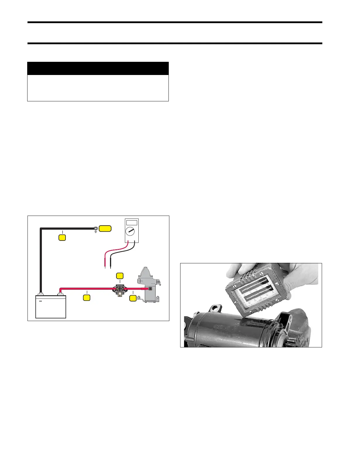
ELECTRIC START TESTS
Starter Voltage Drop Test
Use a digit al voltme ter to me asure the volt age
drop on each section of the start circuit.
If an y vo ltage read ing is greate r than 0.5 VDC
check that connections are clean, tight and free of
corrosion. Clean or replace any corroded or dam-
aged cables or connections.
STEP 1: Con nect voltmet er positive (+) lead to
the terminal for the ne gative (–) batter y cab le at
powerhead. Conn ect vo ltmeter negat ive (–) le ad
to negative (–) battery post.
• Activate st arter motor and ob serve volt age
reading.
STEP 2: Connect positive (+) lead to battery posi-
tive (+) terminal. Connect nega tive (–) lead to
starter solenoid terminal.
• Activate st arter motor and ob serve volt age
reading.
STEP 3: First, activate st arter motor . Conne ct
positive (+) lead to starter solenoid terminal. Con-
nect negative (–) lead to opposite starter solenoid
terminal.
• Observe voltage reading.
STEP 4: Connect positive (+) lead to starter cable
of solenoid terminal. Connect negative (–) lead to
starter motor terminal.
• Activate st arter motor a nd observe volt age
reading.
No Load Current Draw Test
Securely fasten starter in a vise or suitable fixture
before proceeding with this check.
Use a batte ry rated at 500 CCA (60 amp-hr) or
higher that is in good condition and fully charged.
IMPORTANT: The d riven ge ar a nd p inion
assembly must be removed for this test.
Use an inductive ammeter or connect a 0 to 1 00
amp amme ter in series with a heavy jump er
between the b attery positive (+) terminal and t he
starter positive (+) terminal.
Fluke model 33 4 or 336, Snap-On model MT110
or EETA501, and various other ammeters should
be available through local tool suppliers.
Attach or hold a vibration t achometer, such as a
Frahm
†
Reed tachometer, to the starter.
Complete the circuit with a heavy jumper between
the batte ry n egative (–) te rminal a nd t he st arter
frame.
Monitor the starter RPM and current draw.
• At 10 ,500 RPM the a mmeter should sh ow a
maximum of 30 A.
A WARNING
To prevent accidental starting of outboard,
disconnect cranksha ft posi tion sen sor
(CPS).
1. Negative battery cable
2. Positive battery cable
3. Solenoid
4. Starter cable
008464
TYPICAL 24083