107
ELECTRICAL AND IGNITION
ELECTRIC START TESTS
6
Starter Voltage Drop Test
Use a digital voltmeter to measure the voltage
drop on each section of the start circuit.
If any voltage reading is greater than 0.5 VDC
check that connections are clean, tight and free of
corrosion. Clean or replace any corroded or dam-
aged cables or connections.
STEP 1: Connect voltmeter positive (+) lead to
the terminal for the negative (–) battery cable at
powerhead. Connect voltmeter negative (–) lead
to negative (–) battery post.
• Activate starter motor and observe voltage
reading.
STEP 2: Connect positive (+) lead to battery posi-
tive (+) terminal. Connect negative (–) lead to
starter solenoid terminal.
• Activate starter motor and observe voltage
reading.
STEP 3: First, activate starter motor. Connect
positive (+) lead to starter solenoid terminal. Con-
nect negative (–) lead to opposite starter solenoid
terminal.
• Observe voltage reading.
STEP 4: Connect positive (+) lead to starter cable
of solenoid terminal. Connect negative (–) lead to
starter motor terminal.
• Activate starter motor and observe voltage
reading.
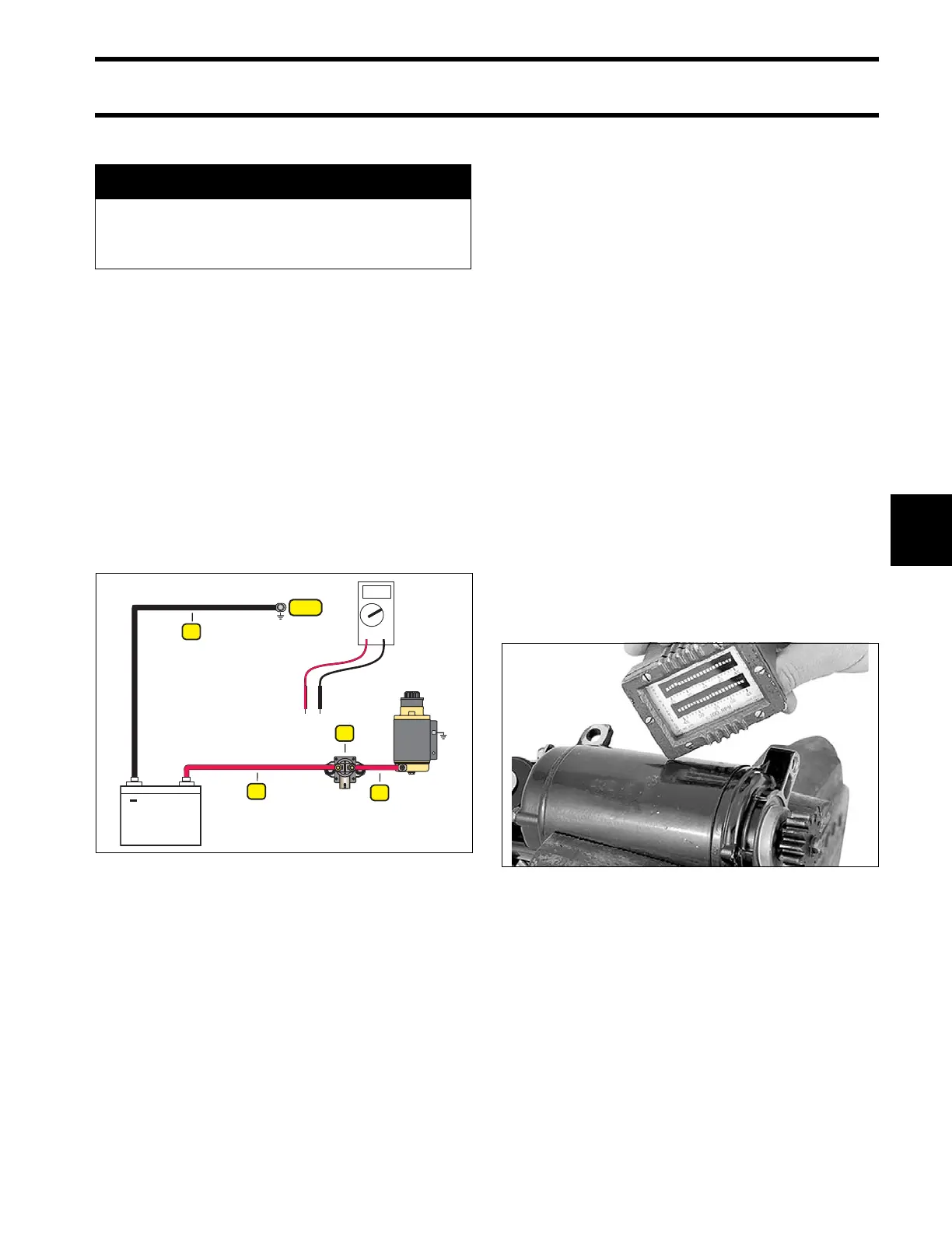
No Load Current Draw Test
Securely fasten starter in a vise or suitable fixture
before proceeding with this check.
Use a battery rated at 500 CCA (60 amp-hr) or
higher that is in good condition and fully charged.
Use an inductive ammeter or connect a 0 to 100
amp ammeter in series with a heavy jumper
between the battery positive (+) terminal and the
starter positive (+) terminal.
Fluke model 334 or 336, Snap-On model MT110
or EETA501, and various other ammeters should
be available through local tool suppliers.
Attach or hold a vibration tachometer, such as a
Frahm
†
Reed tachometer, to the starter.
Complete the circuit with a heavy jumper between
the battery negative (–) terminal and the starter
frame.
Monitor the starter RPM and current draw.
• At 10,500 RPM the ammeter should show a
maximum of 30 A.
A WARNING
To prevent accidental starting of outboard,
disconnect crankshaft position sensor
(CPS).
1. Negative battery cable
2. Positive battery cable
3. Solenoid
4. Starter cable
008464
24083