210
POWERHEAD
POWERHEAD ASSEMBLY
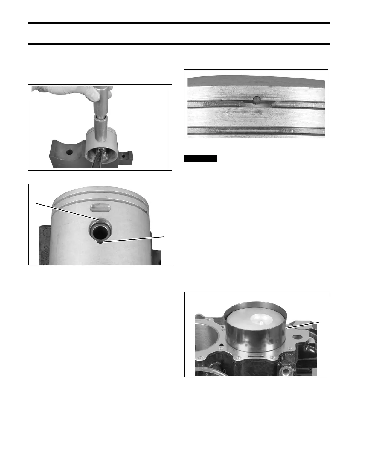
Use Wrist Pin Cone, P/N 318600, and Driver,
P/N 318599, to install new wrist pin retaining rings
in each wrist pin hole. Gap of retaining ring faces
up, away from notch in piston.
Installing Pistons
When all pistons and connecting rods are assem-
bled, install piston ring sets. Be sure rings are
installed in the cylinder used to test ring end gap.
Refer to POWERHEAD INSPECTION on p. 205.
IMPORTANT: Be sure gap of ring fits squarely
around dowel pin.
Before continuing, make sure that
all Gel-Seal II has been removed from the cyl-
inder block and crankcase mating flanges. If
traces of hardened Gel-Seal II are left, main
bearings could be misaligned. Refer to CYLIN-
DER BLOCK CLEANING on p. 204.
Coat pistons, rings, cylinder walls, and an appro-
priate ring compressor with outboard lubricant.
Center connecting rod in piston and locate piston
rings on dowel pins. Place appropriate ring com-
pressor on piston.
Slide piston and rod assembly into the correct cyl-
inder, as marked during disassembly. Guide con-
necting rod through cylinder block to avoid
scratching cylinder wall.
Repeat steps for each piston.
002058
1. Gap of retaining ring
2. Notch in piston
002050
002048
1. Ring compressor 002059