2002 Buell P3: Engine 3-11
HOME
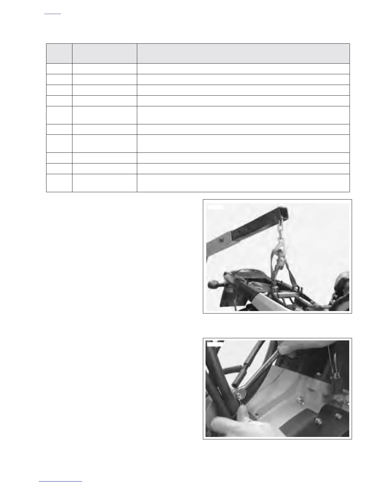
24. See Figure 3-11. Place a floor hoist behind the lift.
Attach straps to frame and hoist. Raise hoist until straps
tighten.
25. Remove rear shock. See 2.15 REAR SHOCK
ABSORBER.
26. See Figure 3-12. Loosen nut on hose routing clamp.
Table 3-3. Electrical Items Disconnected for Engine Disassembly
Item
no.
Description Location
1Ignition module [10] Located on frame backbone.
2Speedo sensor [65] Located under seat (right side-tucked in under cavity).
3Side stand switch [60] Tie wrapped to rear brake line.
4Neutral switch [131] Disconnect at neutral switch.
5Oil pressure switch
[120]
Disconnect at oil pressure switch.
6Alternator stator [46] Located under seat (left side).
7Starter solenoid wire
[128]
Disconnect at starter.
8Spark plug wire Located on spark plug.
9Battery—positive wire Disconnect at main circuit breaker.
10 Rear brake light switch
[121]
Located under frame by shock absorber.
Figure 3-11. Hoisting Bike
Figure 3-12. Loosen Clamp
7650
7718