2002 Buell P3: Electrical 7-31
HOME
System Relay
See Figure 7-35. The system relay is in the relay block which
is located on the left side under the seat. Test the relay as fol-
lows:
1. Remove seat. See 2.28 SEAT.
2. Unplug relay from connector. See “ON-MOTORCYCLE”
TESTS.
3. Test the relay in the same fashion as the starter relay.
See 5.6 STARTER SYSTEM TESTING.
4. Replace the relay with a new relay if necessary. Install
relay to frame with new rivet and washer.
Starter Relay
The starter relay is located on the right side of the motorcy-
cle, underneath the seat by the flasher relay.
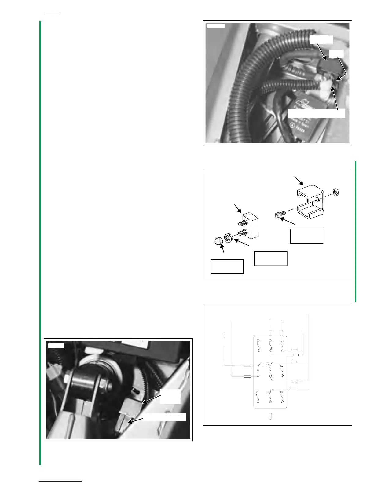
Main Circuit Breaker
See Figure 7-36. Attached to the frame above the battery, the
main circuit breaker is between the ignition key switch and
the battery. Remove the main circuit breaker as follows:
1. Remove seat. See 2.28 SEAT.
2. Disconnect battery negative cable from battery.
3. See Figure 7-37. Remove acorn nuts, nuts with lock
washers and wire leads from circuit breaker studs. Tag
wire leads for ease of assembly.
4. See Figure 7-36. Remove circuit breaker from circuit
breaker bracket by carefully prying tab, located on left
side, open and sliding circuit breaker out. NOTE: Bank
Angle Sensor will require reinstallation if bracket is
removed. See 7.5 BANK ANGLE SENSOR.
5. Install in the reverse order. Tighten screw (if bracket was
removed) to 25-27 in-lbs (2.8-3.1 Nm). Tighten metal nut
to 15-18 in-lbs (1.7-2 Nm). Tighten plastic acorn nuts to
1-3 in-lbs (0.1-0.3 Nm).
Ignition Fuse
See Figure 7-38. The ignition fuse is in the fuse block under
the seat. Always replace the fuse with another 7.5 ampere
fuse.
Figure 7-35. System Relay
7803
System
Relay
Connector [171]
Figure 7-36. Circuit Breaker
Figure 7-37. Circuit Breaker Installation
Figure 7-38. Fuse Block
7811
Bracket
Circuit Breaker (30A)
Tab
a0237x7x
Bracket
Circuit Breaker (30A)
Acorn Nut (2)
Nut with Lock washer (2)
15-18 in-lbs
(1.7-2 Nm)
1-3 in-lbs
(0.1-0.3 Nm)
Screw
25-27 in-lbs
(2.8-3.1 Nm)
TN/W
TN
R
DIODE 1
R2
R/BK
15A
15A
15A
SYSTEM
LIGHTS
15A
KEY SWITCH
DIODE 2
SPARE
TN/Y
TN/GR
O
7.5A
SPARE
7.5A
7.5A
ACCESSORY
IGNITION
TN/Y
R/BK
G
Y
a0234x7x
[61]