44
24VDC - Design
NOTE!
Use of the control head in a potentially explosive atmosphere
` Onlyusecablesandcableglandswhichareapprovedfortherespectiveapplicationareaandtthe
cable glands according to the respective operating instructions!
` Close all unnecessary openings with lock screws/plugs approved for explosions area!
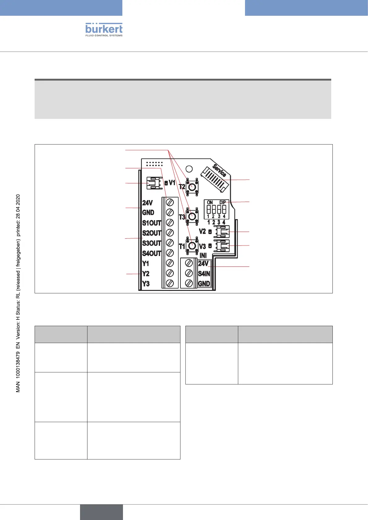
24 V DC Electronic module, terminal strip conguration:
Solenoid valve connec-
tion with status LED
for valve V1
Power supply
Service interface
DIP switches for co-
lour coding the device
status LED / Top LED
Connection for the
external initiator
Feedback signals
S1-S4 OUT
Control solenoid valves
Y1-3
Teach buttons T1-3
Solenoid valve
connections
with status LED
for valves V2, V3
Terminal strip
Fig. 15: 24 V DC electronic module
Designation
Terminal strip
Conguration
Designation
Terminal strip
Conguration
24 V Power supply 24 V 24 V
Power supply 24 V for external
initiator
GND GND S4 IN External initiator input
S1 OUT Output position S1 GND GND external initiator
S2 OUT Output position S2
S3 OUT Output position S3
S4 OUT External initiator output S4
Y1 Solenoid valve V1 input
Y2 Solenoid valve V2 input
Y3 Solenoid valve V3 input
english
Control Head Type 8681