51
120VAC - Design
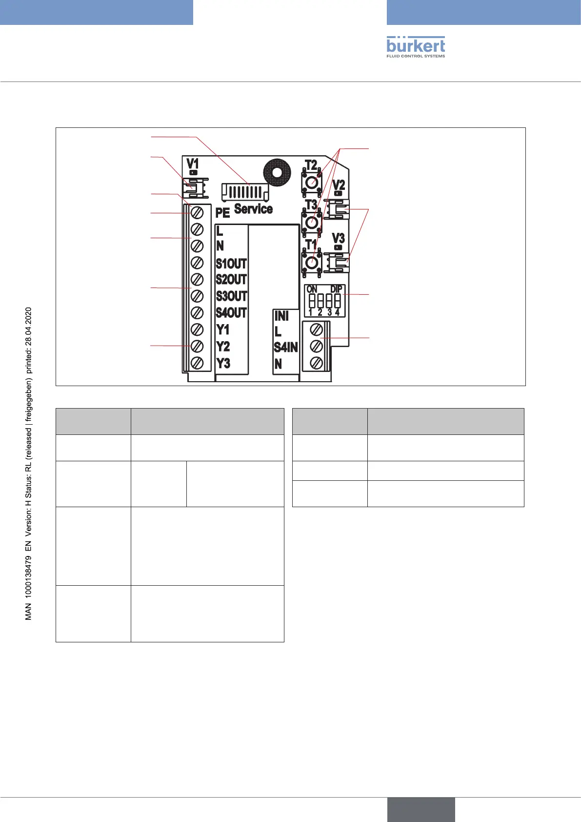
120 V AC Electronic module, terminal strip conguration:
Solenoid valve
connection with status
LED for valve V1
Terminal strip
Service interface
DIP switches for co-
lour coding the device
status LED / Top LED
Connection for
the external initia-
tor
Feedback signals
S1-S4 OUT
Control solenoid
valvesY1-3
Teach buttons T1-3
Solenoid valve connections
with status LED for
valves V2, V3
Protective conductor
(protectiveearth)
Powersupply(L/N)
Fig. 19: 120 V AC electronic module
Designation
Terminal strip
Conguration
Designation
Terminal strip
Conguration for external
initiator
PE
Protective conductor - Protective
Earth
L Power supply - conductor
L Conductor Power S4 IN External initiator input
N
Neutral
conductor
supply 120 V AC N Power supply - neutral conductor
S1 OUT Output position S1
S2 OUT Output position S2
S3 OUT Output position S3
S4 OUT External initiator output S4
Y1 Solenoid valve V1 input
Y2 Solenoid valve V2 input
Y3 Solenoid valve V3 input
english
Control Head Type 8681