52
120VAC - Design
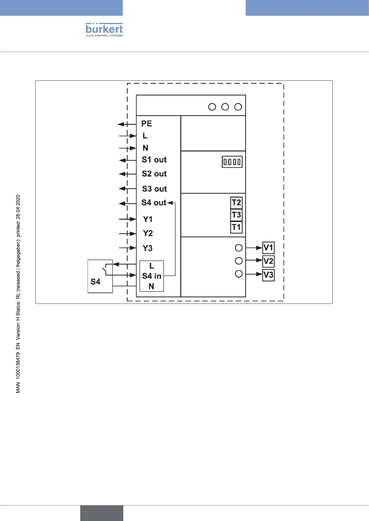
Circuit diagram 120 V AC:
Electronics
Position measuring
system with LEDs
Service interface
DIP switch for LEDs
Teach buttons
Valve
actuation /
control LEDs
for valves
Protective Earthr
Central power supply
120 V AC
Output position 1
(0/120VAC,L-switching)
Output position 2
(0/120VAC,L-switching)
Output position 3
(0/120VAC,L-switching)
Output external initiator
(0/120VAC,L-switching)
Input solenoid valve 1
(0/120VAC)
Input solenoid valve 2
(0/120VAC)
Input solenoid valve 3
(0/120VAC)
Valve 1
Valve 2
Valve 3
Fig. 20: Circuit diagram 120 V AC
english
Control Head Type 8681