C-5
Scanner
®
2000 microEFM Appendix C
• The eldbus interface board includes terminals for Foundation™ eldbus power/communications.
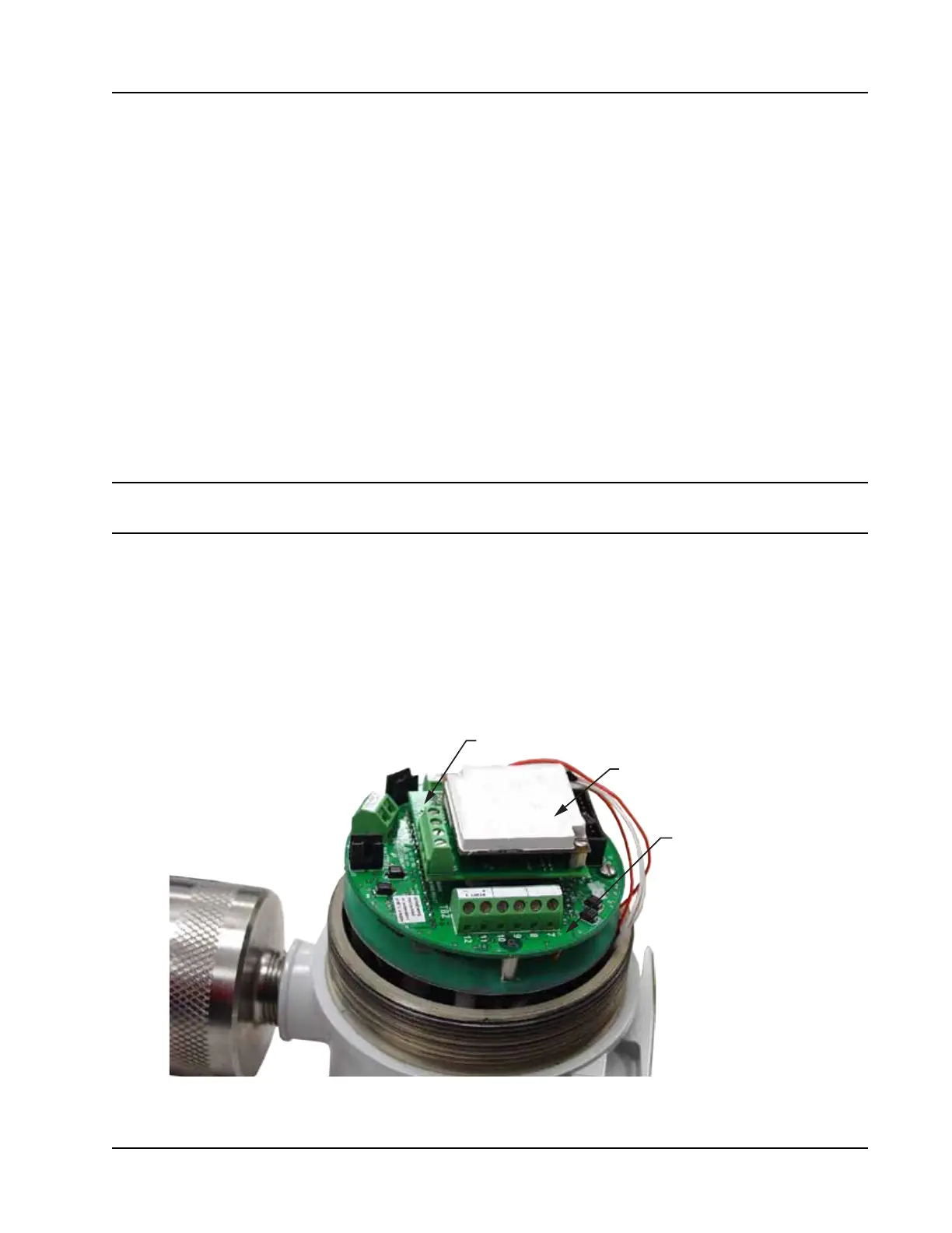
A white potted eldbus module (Figure C.3, page C-5) is attached to the eldbus interface board, but it has
no customer inputs/outputs. It is used solely for converting Modbus
®
signals received from the main board to
Foundation™ eldbus H1 protocol that can be read and transmitted via a eldbus network.
Fieldbus Cable
Use only Type A twisted shielded pair cable to connect the eldbus network to the Scanner 2000. To help
prevent noise, the shield should cover at least 90 percent of the total wire length.
For best performance, adhere to the following best practices for wiring:
• Never run instrument cable next to power cables in cable trays or near heavy electrical equipment.
• Make sure the cable is continuously connected throughout the eldbus segment.
• Make sure the cable is securely connected to an earth ground near the power supply connection.
• If the shield is connected to the enclosure, ensure that the exposed shield connection is as short as pos-
sible to minimize noise.
CAUTION Never connect an instrument signal conductor to a safety ground. Doing so could shut
down the entire eldbus segment.
Basic Wiring
A standard Scanner 2000 with MVT has two conduit openings in the top of its housing for eld wiring.
The following procedure describes the steps for wiring a standard Scanner 2000 for operation using the
eldbus power supply and one additional input or output. If additional inputs/outputs are required, a terminal
housing (junction box) is recommended. See Terminal Housing, page A-16 and Terminal Housing Wiring Options,
page C-8.
Fieldbus interface board
Fieldbus module
Main circuit board
Figure C.3—Circuit board arrangement