C-17
Scanner
®
2000 microEFM Appendix C
Board Replacement
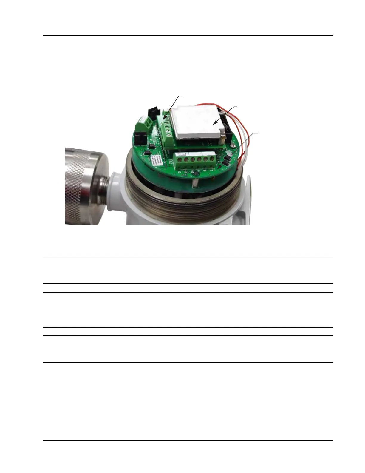
The Scanner 2000 electronic circuitry includes three boards (Figure C.8). The main board (on bottom of the
board stack when the assembly is removed from the enclosure) is attached to a smaller eldbus interface
board, which is in turn attached to a white potted eldbus module. Only the main board and eldbus interface
board have input/output eld connections.
Fieldbus interface board
Fieldbus module
Main circuit board
Figure C.8—Circuit board arrangement
Main Board
Important Static electricity can damage a circuit board. Handle new boards only by their edges,
and use proper anti-static techniques (such as wearing anti-static wrist strap or touching
metal to establish an earth ground) prior to handling a board.
Important If possible, download the conguration settings and all archive logs before replacing the
circuit board. Press the ENTER/SAVE key on the keypad before disconnecting the bat-
tery to save accumulated ow run and turbine volume totals (grand total and current day
total), and energy and mass totals to memory.
Important The interface board is attached securely to the main board by a standoff that is not vis-
ible when all three boards are assembled. The interface board cannot be removed from
the main board without rst removing the white potted module to access the standoff.
To replace the main board, perform the following steps:
1. Unscrew the cover from the enclosure and set it aside.
2. Using a small standard blade screwdriver, remove the two #4-40 × 7/8” screws located to the right and
left side of the display (Figure C.9).
3. Lift the board assembly from the enclosure, taking precautions to avoid straining the sensor ribbon cable
connection.