C-18
Appendix C Scanner
®
2000 microEFM
4. Record the locations of all cable connections to the main board.
5. Disconnect the eldbus input cable from terminal block TB4 on the eldbus interface board (Figure C.9).
6. Unplug the battery cable from connector J1 on the main board (Figure C.9).
7. Using a small standard blade screwdriver, remove all wiring from terminal blocks TB1, TB2, and TB3,
ensuring that all wiring that is connected to powered circuits is insulated with tape.
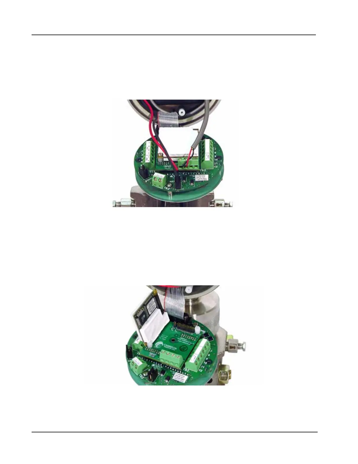
Figure C.9—Removal of the battery cable and eldbus interface board cable
8. Remove the two screws that attach the white potted eldbus module to the eldbus interface board, and
remove the module from the interface board (Figure C.10, page C-18).
9. The interface board is rmly connected to the main board with a plastic standoff. Using small pliers,
squeeze the two halves of the standoff together while applying rm pressure to separate the interface
board from the main board. Proceed with care to avoid bending the pins on the interface board. With the
eldbus module and the eldbus interface removed, the main board will be in full view (Figure C.11,
page C-19).
Figure C.10—Removal of white potted eldbus module