Home
Cameron
Measuring Instruments
Scanner 2000 microEFM
Cameron Scanner 2000 microEFM User Manual
5
of 1
of 1 rating
190 pages
Give review
Manual
Specs
To Next Page
To Next Page
To Previous Page
To Previous Page
Loading...
C-19
Scanner
®
2000 microEFM
Appendix C
Figure C.1
1—Removal of the eldbus interface board
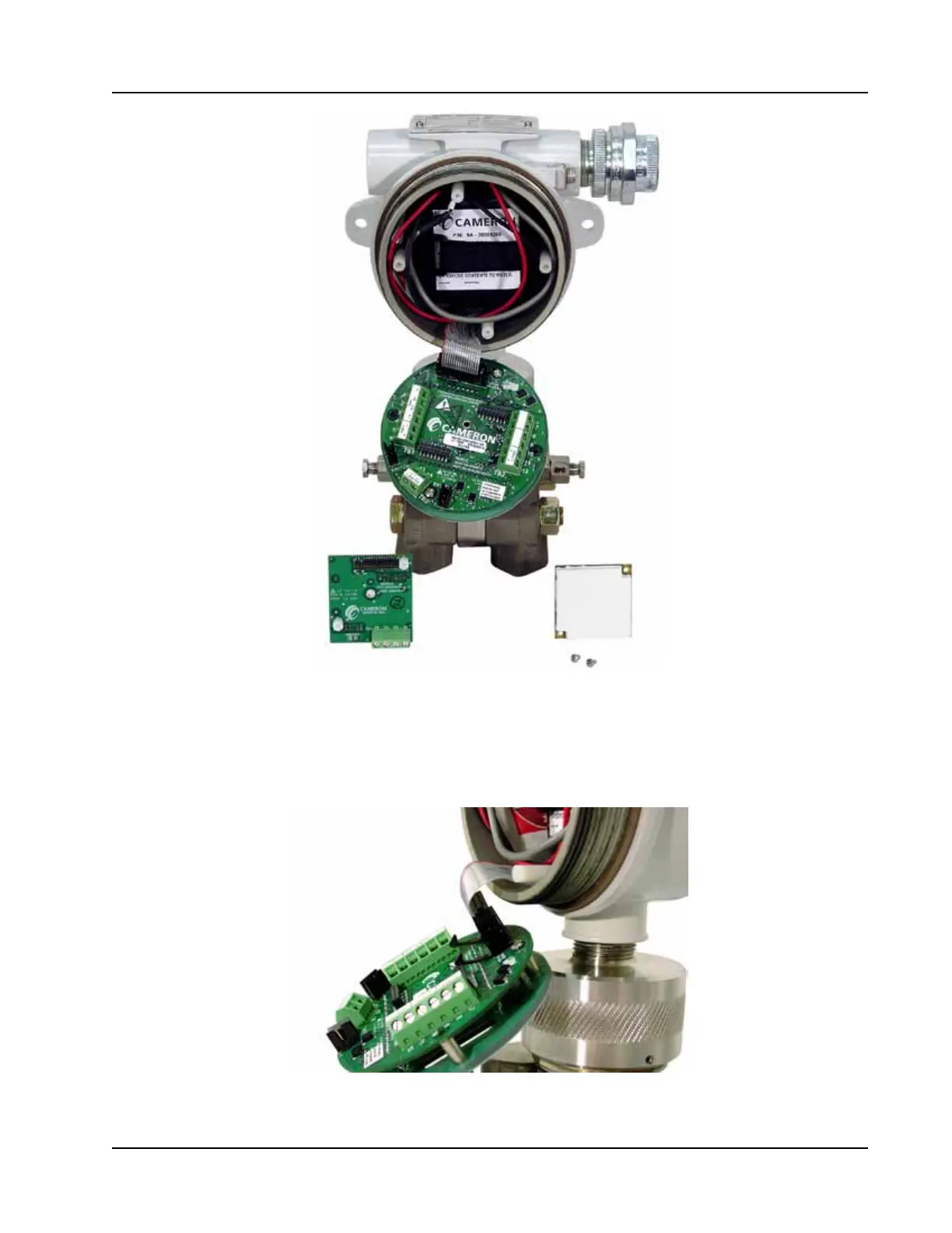
10.
Disconnect the sensor ribbon cable from the J5 connector on the main board as follows:
a.
Lift the latch from the black clip securing the ribbon cable (Figure C.12).
b.
When the latch is fully open, the ribbon cable will release freely
.
Figure C.12—Latch securing the ribbon cable
124
126
Table of Contents
Default Chapter
2
Important Safety Information
2
Table of Contents
3
Section 1-Introduction
7
Flow Rate and Fluid Property Calculations
8
Natural Gas
8
Steam
8
Compensated Liquid
9
Uncompensated Liquid
9
Standard Features
10
Product Identification
12
Hardware Options
12
Table 1.1—Scanner 2000 Microefm Specifications
15
Power Options
21
Interface Software Functions
21
Lcd/Keypad Functions
22
Viewing Real-Time Measurements
23
Configuring Basic Parameters
24
Viewing Daily and Hourly Logs
24
Password-Protected Security
25
Section 2-Installing the Scanner 2000
27
Overview
27
Hazardous Area Installations
27
Zone 1 (ATEX) Installations
27
Class I, DIV. 1 (CSA) Installations
28
Class I, DIV. 2 (CSA) Installations
29
Pressure Safety Precautions
29
Mounting Options
30
Pole-Mount Installation
30
Measuring Natural Gas Via a Differential Pressure Meter
33
Best Practices for Orifice and Cone Meter Installation
33
Installation Procedure-Direct Mount to Orifice Meter or Cone Meter
34
Installation Procedure-Remote Mount to Orifice Meter or Cone Meter
35
Measuring Natural Gas Via a Turbine Meter
38
Best Practices
38
Installation Procedure-Remote Mount to a Turbine Meter
38
Installation Procedure-Direct Mount to a Turbine Meter (CSA Compliant)
40
Measuring Steam Via a Differential Pressure Meter
42
Best Practices
42
Installation Procedure-Remote Mount to Orifice Meter or Cone Meter
43
Measuring Liquid Via a Differential Pressure Meter
46
Best Practices
46
Installation Procedure-Direct Mount to Orifice Meter or Cone Meter
47
Installation Procedure-Remote Mount to Orifice Meter or Cone Meter
48
Measuring Compensated Liquid Via a Turbine Meter
51
Best Practices
51
Installation Procedure-Direct Mount to a Turbine Meter (CSA Compliant)
51
Installation Procedure-Direct Mount to a Barton 7000 Series Turbine Meter (ATEX Compliant)
52
Measuring Uncompensated Liquid Via a Turbine Meter
54
Best Practices
54
Installation Procedure-Direct Mount to a Turbine Meter (CSA Compliant)
54
Installation Procedure-Direct Mount to a Barton 7000 Series Turbine Meter (ATEX Compliant)
55
Performing a Manifold Leak Test
55
Zero Offset (Static Pressure or Differential Pressure)
56
Static Pressure Calibration and Verification
56
Differential Pressure Calibration and Verification
57
Placing the Scanner into Operation
58
Industry Standard Compliance
58
Industry Standards for Cone Meters
59
Table 2.2—Industry Standards for Orifice Meters
59
Table 2.3—Industry Standards for Turbine Meters
60
Section 3-Wiring the Scanner 2000
61
Field Wiring Connections
61
Grounding Procedures
62
Power Supply Wiring
63
Internal Power Supply
63
External Power Supply
64
Input Wiring
65
Turbine Flowmeter Input
65
RTD Input
66
Output Wiring
67
Digital Output (Pulse or Alarm)
67
RS-485 Output-Permanent Computer Connection
68
RS-485 Output-Laptop Computer Connection
69
Configuration Via Keypad
70
Configuration Via Modworx™ Pro Software
70
Section 4-Configuration and Operation Via Keypad
71
Entering the Slave Address
72
Entering the Baud Rate
73
Editing the Date and Time
74
Editing the Contract Hour
75
Editing the Plate Size
76
Section 5-Scanner 2000 Maintenance
77
Lithium Battery Pack Replacement
77
Circuit Assembly Replacement
78
Keypad Replacement
81
MVT Replacement
82
Section 6-Spare Parts
83
Table 6.2—Scanner 2000 Microefm Spare Parts (ATEX-Approved)
84
Table 6.3—RTD and Cable Assemblies (CSA-Approved)
85
Appendix A-Scanner 2000 Hardware Options
87
Explosion-Proof Control Switch
87
RTD Assemblies
89
Weatherproof RTD Assembly (CSA, Class I, DIV. 2
89
Explosion-Proof RTD Assembly (CSA, Class I, DIV. 1
89
Flameproof RTD Assembly (ATEX, Zone 1
89
Communications Adapter (CSA DIV. 1 or DIV. 2, ATEX Zone 1
90
Communications Adapter Installation (for Adapters Purchased Separately from a Scanner 2000
92
USB Communications Adapter (CSA DIV. 1 or DIV. 2
92
Covering the Adapter
92
Using the Adapter
93
Adapter Kit Installation
94
Input/Output Expansion Board (Not Available with Fieldbus
94
Installation (for Boards Purchased Separately from a Scanner 2000
95
Wiring Diagrams
96
Measurement Canada Seal Kit
100
Seal Kit Installation
100
Terminal Housing
102
Appendix B-Lithium Battery Information
105
Lithium Battery Disposal
105
Transportation Information
105
Material Safety Data Sheet
105
Appendix C-Scanner 2000 for F Overview
107
Oundation ™ Fieldbus
107
Appendix C-Scanner 2000 for F Oundation™ Fieldbus
108
Hardware Options
108
Specifications
108
Installing the Scanner 2000
109
Control System Components
109
Mounting Options
110
Field Wiring Connections
110
Fieldbus Cable
111
Basic Wiring
111
Grounding Procedures
112
Lithium Battery Pack
113
F Oundation ™ Fieldbus Power Supply
113
Terminal Housing Wiring Options
114
Device Configuration
115
Fieldbus Configuration
115
Device Description
116
Block Descriptions
116
Device Identification
117
Configuring Fieldbus Communications
118
Fieldbus Operations
121
Engineering Units
121
Status
121
Fieldbus Troubleshooting
121
General Errors
121
Communication Faults
122
Maintenance
122
Board Replacement
123
Spare Parts
128
Appendix D-Modbus ® Communications Protocol
129
Introduction
129
Supported Commands
129
Data Types
130
Security
131
Registers
131
Product Code
133
Firmware Version/Register Table Version
133
Manufacture Date/Sales Date
133
Analog Input 1 Calibration
144
Analog Input 2 Configuration
145
Analog Input 2 Calibration
145
Digital Input Configuration
146
Flow Rate Calculation Register
149
Fluid Property Register
150
Tap Type Register
151
Output Configuration
152
Pulse Input for Status Indication
153
Flow Calculation Parameter Registers (1-16
162
Base Units/Configured Units
162
Polling Registers
162
Interval/Daily/Event Pointer Registers
163
User-Defined Modbus ® Registers Configuration
171
Device Status
173
Enron Log Data
176
Appendix E-Fieldbus Communications Protocol
179
Device Properties
179
Parameter Tables
179
Table E.2—Transducer Block Parameters
181
Table E.3—Analog Input Block Parameters
183
Control Registers
185
Table E.4—Transducer Error (Xd_Error) and Block Alarm Codes
185
Unit Conversion
186
5
Based on 1 rating
Ask a question
Give review
Questions and Answers:
Need help?
Do you have a question about the Cameron Scanner 2000 microEFM and is the answer not in the manual?
Ask a question
Cameron Scanner 2000 microEFM Specifications
General
Brand
Cameron
Model
Scanner 2000 microEFM
Category
Measuring Instruments
Language
English
Related product manuals
Cameron Scanner 3100 EFM
100 pages
Cameron BARTON 289A
75 pages
Cameron Barton 199
32 pages
Cameron NUFLO MC-III
120 pages
Cameron NUFLO MC-III EXP
143 pages
Cameron NuFlo MC-II
47 pages
Cameron NUFLO EZ-IN Series
32 pages