E-7
Scanner
®
2000 microEFM Appendix E
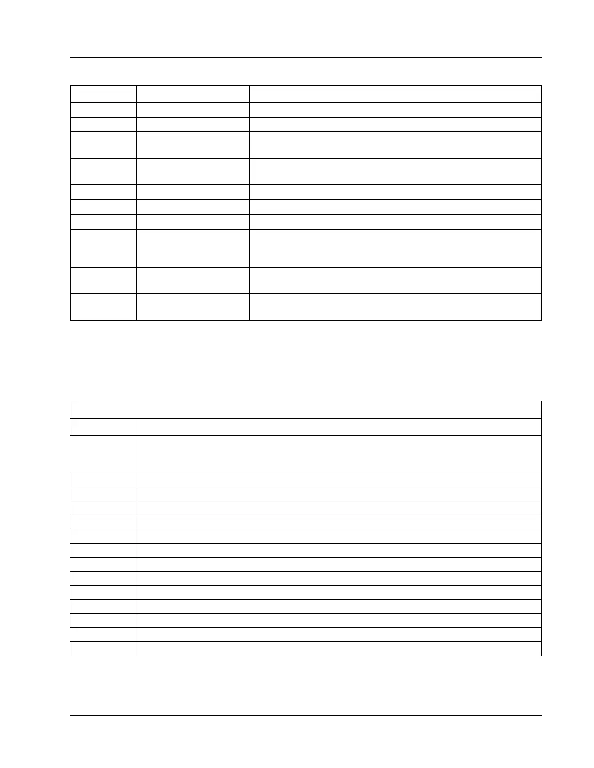
Table E.4—Transducer Error (XD_Error) and Block Alarm Codes
Value Error Description
16 Unspecied error Indicates occurrence of unidentied error
17 General error Error cannot be classied as one of the following errors
18 Calibration error Error occurred during calibration of the device or calibration error
detected during device operation
19 Conguration error Error occurred during conguration of the device or conguration
error detected during device operation
20 Electronics failure Electronic component has failed
21 Mechanical failure Mechanical component has failed
22 I/O failure I/O failure has occurred
23 Data integrity error Data stored within the system may no longer be valid due to non-
volatile memory checksum failure, data verify after write failure,
etc.
24 Software error Software has detected an error. Possible causes: improper
interrupt service routine, arithmetic overow, watchdog timer, etc.
25 Algorithm error Algorithm used in the transducer block produced an error.
Possible causes: overow, data reasonableness failure, etc.
Control Registers
The Control Registers allow specic functions to be implemented via the communications port.
Table E.5 shows the value to be written to the control register to implement the desired function.
Table E.5—Control Registers
Code Function
20000 Transfers the polling totals and averages and polling run times to the previous polling totals,
averages and previous run-time registers, increments the polling index register, and resets
the polling totals, averages and polling run-time registers.
30000 Clears all ow totals
30001 Clears Flow Run 1 totals
30003 Clears Turbine 1 totals
30004 Clear Turbine 2 totals
30050 Clears all pulse output latches
30051 Clears a Pulse Output 1 latch
30061 Adds pulses specied in Control Register 2 to Pulse Output 1 Accumulator
30100 Clear all Alarm States
30101 Clear Flow Run Alarm Status
30102 Clear Input Alarm Status
40000 Loads factory defaults
40040 Resets the microcontroller (watchdog)
50050 Creates a partial archive record (daily and interval)