A-8
Appendix A Scanner
®
2000 microEFM
!
WARNING: When a hazardous area is present, ensure the union nut and blanking plug are
properly tted in the conduit opening. The explosion-proof rating applies only when the union
nut and blanking plug are secured in place. When the union is broken, the device is no longer
explosion-proof.
!
WARNING: Before disassembling the union nut and blanking plug, make sure the area is non-
hazardous.
Adapter Kit Installation
If the NuFlo USB adapter is purchased as a kit, install it in the Scanner 2000 according to the steps below.
The USB adapter is comprised of a USB adapter socket, a blanking plug, and a union nut. The blanking plug
and union nut are connected to the adapter only when the USB port is not in use.
1. Remove the plug from a conduit opening in the Scanner 2000 enclosure.
2. Thread the cable of the adapter through the conduit opening and screw the adapter into place.
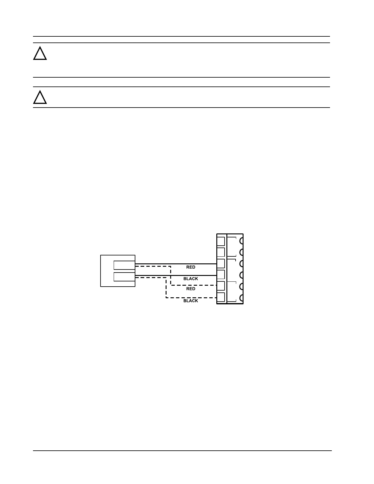
3. Wire the adapter cable to either communications port on the Scanner 2000 main circuit board as shown in
the wiring diagram (black wire to negative terminal).
4. If the USB port will not be used immediately, nest the blanking plug inside the union nut and screw the
union nut onto the adapter to cover the USB socket. Hand-tighten to ensure a snug connection.
POWER PORT 2 PORT 1
–
+
–
+
–
+
7
8
9
10
11
12
PORT 1 OR PORT 2 CAN BE
CONNECTED TO THE USB ADAPTER
USB
CONNECTOR
Figure A.13—Wiring of NuFlo USB adapter (required only when purchased as a kit)
Input/Output Expansion Board (Not Available with Fieldbus)
With the installation of the Scanner 2000 input/output expansion board, the instrument can support up to three
ow runs simultaneously—a ow run and two turbine meter runs. All inputs and outputs are congured with
ModWorX™ Pro software provided with each Scanner 2000 microEFM. See the ModWorX™ Pro Software
User Manual, Part No. 9A-30165025, for details.
The expansion board shown in Figure A.14, page A-9, includes the following inputs and outputs:
• 2 analog inputs (can be congured for 0-5 V, 1-5 V or 4-20 mA)
• 1 turbine meter input
• 1 pulse input
• 1 analog output (4-20 mA)