52
Section 2 Scanner
®
2000 microEFM
To connect the Scanner 2000 to a liquid turbine meter using this method, perform the following steps:
1. Position the Scanner 2000 above the owmeter.
2. Plug the Scanner 2000 cable connector into the magnetic pickup of the turbine meter and hand-tighten the
knurled nut on the connector.
3. Screw the Scanner 2000 onto the owmeter threads surrounding the magnetic pickup with the display fac-
ing the desired direction.
CAUTION Do not use Teon
®
tape on the threads of the union, adapter, or pipe plugs. Use of
Teon
®
tape will void the explosion-proof rating of the instrument.
4. Tighten all sections of the pipe union.
5. Install the RTD assembly in the thermowell. Remove the plug from a conduit opening in the top of the
Scanner 2000 enclosure, route the RTD assembly cable through the conduit opening and connect it to the
main circuit board. A wiring diagram for the RTD assembly is provided in Figure 3.5, page 66. For hazard-
ous areas, review Hazardous Area Installations, page 27.
Installation Procedure—Direct Mount to a Barton 7000 Series Turbine
Meter (ATEX Compliant)
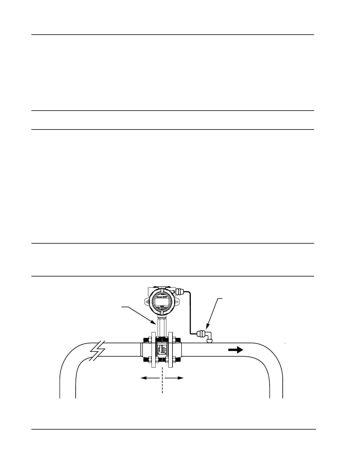
A Scanner 2000 without the MVT bottomworks can be mounted directly to a Barton 7000 series turbine meter
for measuring liquid (Figure 2.13). A stainless steel turbine meter pickup extension supports the Scanner 2000
and provides the elevation necessary for good visibility of the display.
WARNING HAZARDOUS AREA USE. The Scanner 2000 is certied for hazardous area use only when
installed in accordance with applicable standards and local wiring practices. Carefully
review Hazardous Area Installations, page 27, to determine specic installation require-
ments (cable glands, conduit seals, signal cable, RTD, etc.).
Flow
Turbine meter pickup
extension (ATEX-approved)
10 pipe diameters
upstream (minimum)
5 pipe diameters
downstream (minimum)
ATEX-approved
explosion-proof RTD
Figure 2.13—Direct-mount installation for use with a Barton 7000 Series meter