69
Scanner
®
2000 microEFM Section 3
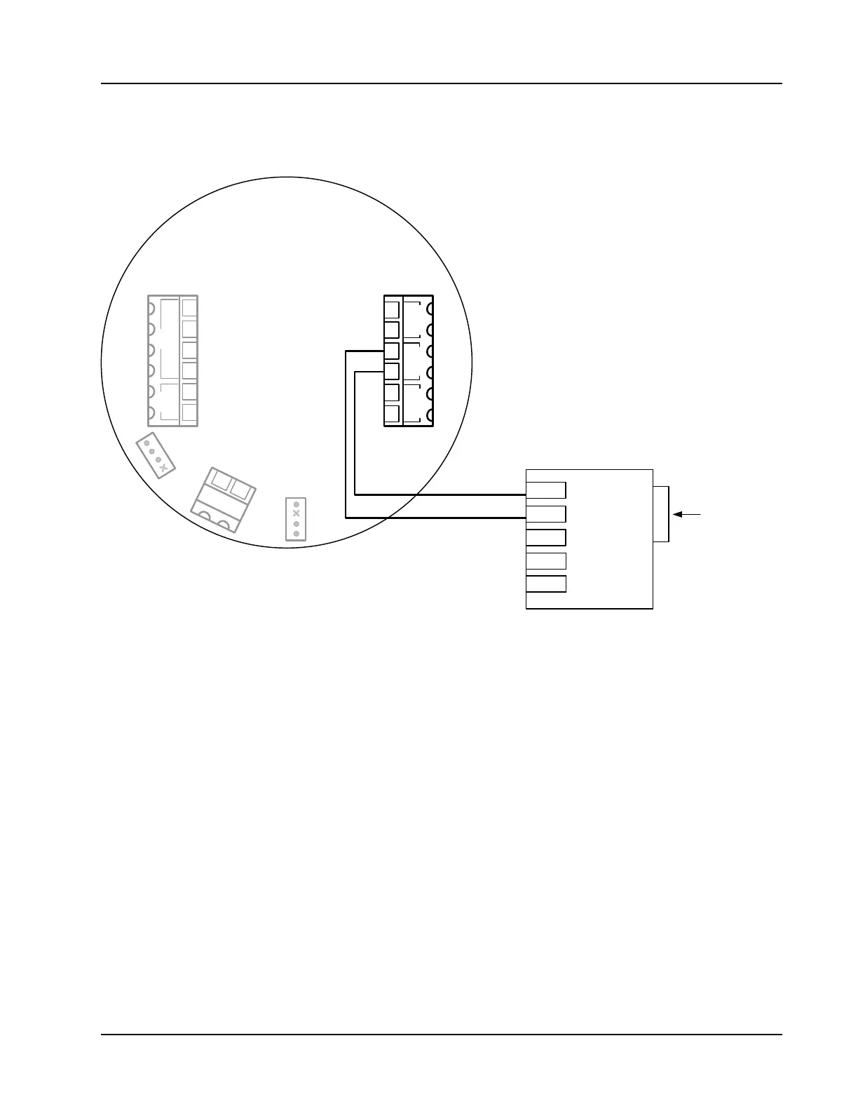
RS-485 Output—Laptop Computer Connection
The RS-485 output is required for communication with the interface software. The wiring diagram in Figure
3.8 supports a temporary laptop connections using an RS-232 to RS-485 converter.
TD(A)
TD(B)
GND
RS-232
9 - PIN
CONNECTOR
Part No. 9A-101283116
TX-
TX+
TB1 TB2
POWER
TFM 1 RTD
PORT 2 PORT 1
I
+
R
+
R
-
I
-
SCANNER 2000
Main Circuit Board
PN: 9A-30160010
–
+
–
+
–
+
–
+
2
3
4
5
6
1
J1
TB3
BATTERY
13
14
J2
7
8
9
10
11
12
SWITCH
DIG OUT 1
GND
+12V
PORT 2 CONNECTIONS ARE
SHOWN IN THIS DIAGRAM.
TO USE PORT 1:
CONNECT TD(B) TO TERMINAL 11 (+).
CONNECT TD(A) TO TERMINAL 12 (-).
Figure 3.8—RS-485 output (connection to laptop with 9-pin converter)