43
Scanner
®
2000 microEFM Section 2
CAUTION Before starting the system, remove the caps and add water or antifreeze if necessary to
completely ll the pots and cold legs. Air trapped in the lines will produce errors in dif-
ferential pressure measurements.
Installation Procedure—Remote Mount to Orice Meter or Cone Meter
A Scanner 2000 can be mounted remotely and connected to an orice meter or cone meter with tubing for
steam measurement. The setup of the meter run and plumbing congurations can vary widely, depending
upon the challenges existing on location.
WARNING HAZARDOUS AREA USE. The Scanner 2000 is certied for hazardous area use only when
installed in accordance with applicable standards and local wiring practices. Carefully
review Hazardous Area Installations, page 27, to determine specic installation require-
ments (cable glands, conduit seals, signal cable, RTD, etc.).
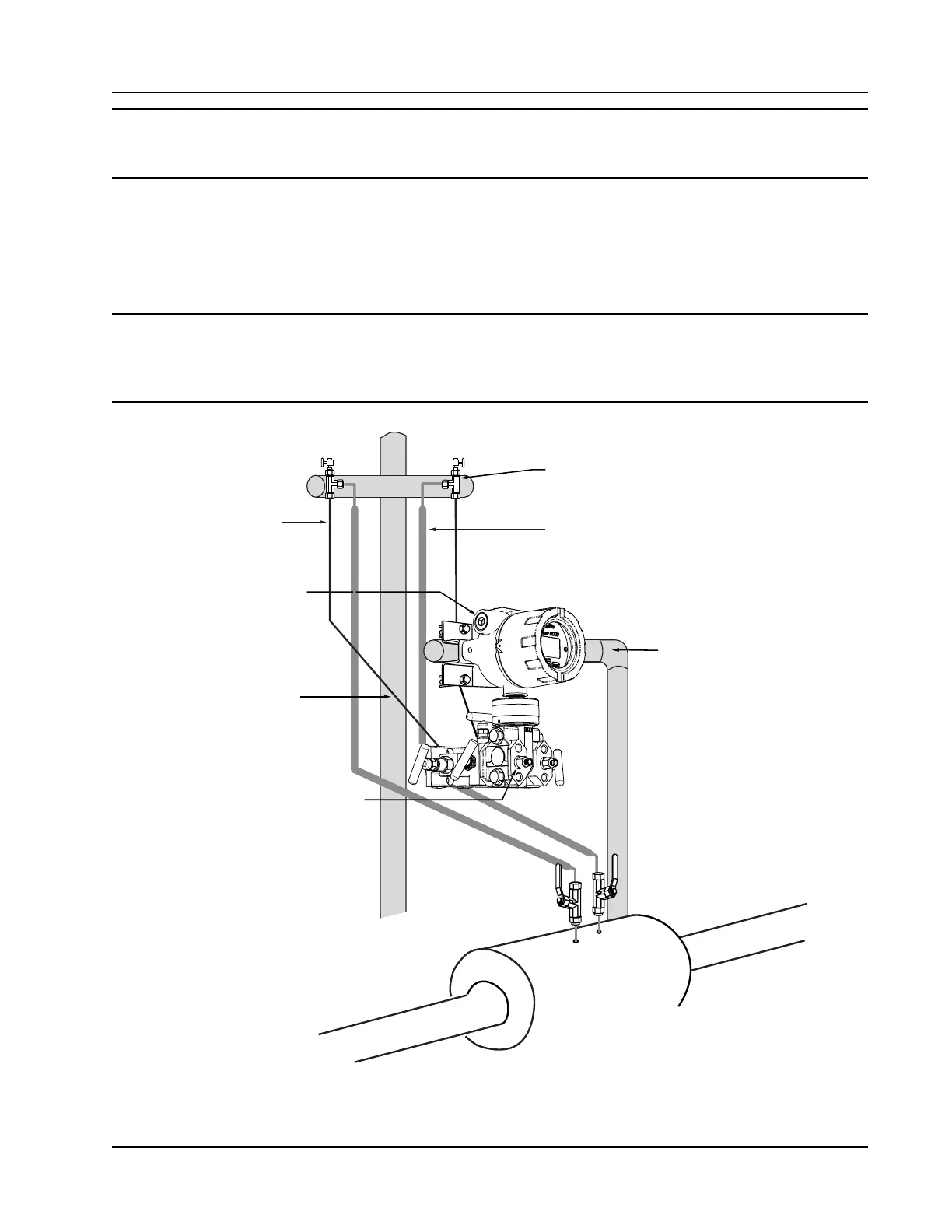
3/4 in. conduit connection for
input/output & communications
Cold legs connect to manifold
(slope to eliminate air trap)
Condensate pot (pipe tee
with blowdown valve attached)
Long cold legs protect the
sensor from extreme process
temperatures
Hot legs, insulated to within 1 ft of condensate pot
(1/2 in. diameter recommended)
MVT vent (use for
for filling cold legs)
Horizontal pole mount provides
clearance for block manifold
Figure 2.9—Remote-mount steam run installation (shown here with a cone meter). The remote-mount method
can be used with an orice meter as well.