67
Scanner
®
2000 microEFM Section 3
Output Wiring
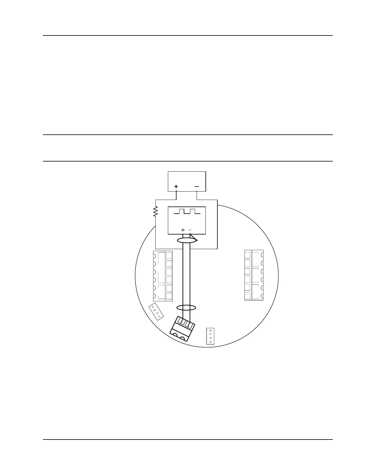
Digital Output (Pulse or Alarm)
The standard Scanner 2000 supports a solid-state digital output that is congurable as either a pulse output or
an alarm output. As a pulse output, the pulse width duration and pulse representation are both congurable.
Because the circuit is isolated, it can be used in conjunction with any other feature on the Scanner 2000. A
two-conductor cable from the Scanner 2000 to the remote location is required. The maximum rating of the
digital output circuit is 60 mA at 30 VDC. Maximum frequency is 50 Hz. Wire as shown in Figure 3.6.
For reduced power consumption, turn the digital output feature off when it is not in use.
Important If the main circuit board is marked with a revision level of 02 or older (revision 01, C, B,
or A), a zener diode (Part No. IN4752) must be installed for CE approval. The zener diode
is not required for revision 03 and newer circuit boards.
J1
TB1
TB2
TB3
BATTERY
13
14
J2
POWER
TFM 1 RTD
PORT 2
PORT 1
I
+
R
+
R
-
I
-
SCANNER 2000
Main Circuit Board
PN
:
9A-30160010
–
+
–
+
–
+
–
+
2
3
4
5
6
1
Leave the end of this
shield disconnected.
Resistor may be included
in pulse readout device.
Size the resistor to limit
the current to 60 mA.
7
8
9
10
11
12
SWITCH
DIG OUT 1
PULSE READOUT
DEVICE
POWER SUPPLY
5 to 30 VDC
Figure 3.6—Pulse output wiring